
In earlier parts of this series, we designed, configured, and optimized IPv4 routing using OSPFv2 across single-area and multi-area topologies. This post transitions to native IPv6 routing using OSPFv3 (RFC 5340) on Nokia SR OS.
OSPFv3 decouples protocol operations from IPv4 addressing semantics. It runs on a per-link basis rather than a per-subnet basis, negotiates adjacencies over IPv6 Link-Local addresses, and introduces separate Link-State Advertisement (LSA) types to decouple topological structure from IP prefix reachability.
- SR OS Version: 25.7.R1
- CLI Mode: MD-CLI (Model-Driven CLI)
The Dual-Stack Architecture (“Ships in the Night”)
Because this deployment builds upon the existing OSPFv2 topology from previous parts of the series, the network operates in a concurrent Dual-Stack model.
In Nokia SR OS, OSPFv2 (ospf 0) and OSPFv3 (ospf3 0) run as completely independent protocol instances, a design often termed “Ships in the Night”:
- Independent Protocol Instances: OSPFv2 and OSPFv3 maintain separate protocol control blocks, distinct Link-State Databases (LSDBs), and separate SPF calculation trees.
- Independent Forwarding Tables: OSPFv2 populates the IPv4 route table (
show router route-table), while OSPFv3 populates the IPv6 route table (show router route-table ipv6). - Shared Physical Substrate: Both protocol instances share the identical physical ports, hybrid ethernet interfaces, and link-level MTU settings without protocol interaction.
OSPFv2 vs. OSPFv3 LSA Architecture
The most critical architectural distinction between OSPFv2 and OSPFv3 is how the Link-State Database handles IP prefix information. In OSPFv2, Type 1 Router LSAs advertised both link topology and IPv4 subnets, causing any subnet change to trigger a full Dijkstra SPF calculation across the entire area.
OSPFv3 (RFC 5340) resolves this by strictly decoupling topology from prefixes:
| LSA Function | OSPFv2 (RFC 2328) | OSPFv3 (RFC 5340) | Nokia SR OS LSA Type | Flooding Scope |
|---|---|---|---|---|
| Router Topology | Type 1 (Router LSA) — Carried topology + subnets | Type 1 (0x2001) — Topology only (no IP prefixes) | Router | Area (0x2000) |
| Transit Network | Type 2 (Network LSA) | Type 2 (0x2002) | Network | Area (0x2000) |
| Inter-Area Prefixes | Type 3 (Network Summary) | Type 3 (0x2003) | IE Pfx | Area (0x2000) |
| ASBR Reachability | Type 4 (ASBR Summary) | Type 4 (0x2004) | Inter-Area-Rtr | Area (0x2000) |
| External Routes | Type 5 (AS External) | Type 5 (0x4005) | External | AS (0x4000) |
| NSSA External | Type 7 (NSSA LSA) | Type 7 (0x2007) | NSSA | Area (0x2000) |
| Link-Local & Prefixes | None | Type 8 (0x0008) (New) | Link | Link-Local (0x0000) |
| Prefix Reachability | None (Bundled in Type 1) | Type 9 (0x2009) (New) | IA Pfx | Area (0x2000) |
Prerequisites: Core IPv6 Addressing Plan
Before configuring OSPFv3, configure IPv6 addresses across all interfaces using explicit prefix lengths:
| Router | Role | System Loopback (/128) | Interfaces & Subnets (/64) |
|---|---|---|---|
| R1 | CE1 | fd50:2026::1 | toR2 (1/1/c1/1): fd50:2026:12::1 |
| R2 | PE1 (ABR) | fd50:2026::2 | toR1 (1/1/c1/1): fd50:2026:12::2toR3 (1/1/c2/1): fd50:2026:23::1toR4 (1/1/c3/1): fd50:2026:24::1 |
| R3 | P1 (Area 0) | fd50:2026::3 | toR2 (1/1/c1/1): fd50:2026:23::2toR5 (1/1/c2/1): fd50:2026:35::1 |
| R4 | P2 (Area 0) | fd50:2026::4 | toR2 (1/1/c1/1): fd50:2026:24::2toR5 (1/1/c3/1): fd50:2026:45::1 |
| R5 | PE2 (ABR) | fd50:2026::5 | toR3 (1/1/c2/1): fd50:2026:35::2toR4 (1/1/c3/1): fd50:2026:45::2toR6 (1/1/c1/1): fd50:2026:56::1 |
| R6 | CE2 | fd50:2026::6 | toR5 (1/1/c1/1): fd50:2026:56::2 |
Part 1: Configuring Single-Area OSPFv3 (Area 0 Baseline)
Objective
Enable OSPFv3 across provider core and edge routers (R2, R3, R4, and R5) within a single backbone area (Area 0) to validate core reachability before introducing multi-area hierarchy.
Router Configuration
Router R2 (PE1 - Core Interfaces)
edit-config global
/configure router interface "system" ipv6 address fd50:2026::2 prefix-length 128
/configure router interface "toR3" ipv6 address fd50:2026:23::1 prefix-length 64
/configure router interface "toR4" ipv6 address fd50:2026:24::1 prefix-length 64

/configure router ospf3 0 admin-state enable
/configure router ospf3 0 area 0 interface "system" interface-type point-to-point passive true
/configure router ospf3 0 area 0 interface "toR3" interface-type point-to-point
/configure router ospf3 0 area 0 interface "toR4" interface-type point-to-point
commit
Router R3 (P1)
edit-config global
/configure router interface "system" ipv6 address fd50:2026::3 prefix-length 128
/configure router interface "toR2" ipv6 address fd50:2026:23::2 prefix-length 64
/configure router interface "toR5" ipv6 address fd50:2026:35::1 prefix-length 64

/configure router ospf3 0 admin-state enable
/configure router ospf3 0 area 0 interface "system" interface-type point-to-point passive true
/configure router ospf3 0 area 0 interface "toR2" interface-type point-to-point
/configure router ospf3 0 area 0 interface "toR5" interface-type point-to-point
commit
Router R4 (P2)
edit-config global
/configure router interface "system" ipv6 address fd50:2026::4 prefix-length 128
/configure router interface "toR2" ipv6 address fd50:2026:24::2 prefix-length 64
/configure router interface "toR5" ipv6 address fd50:2026:45::1 prefix-length 64

/configure router ospf3 0 admin-state enable
/configure router ospf3 0 area 0 interface "system" interface-type point-to-point passive true
/configure router ospf3 0 area 0 interface "toR2" interface-type point-to-point
/configure router ospf3 0 area 0 interface "toR5" interface-type point-to-point
commit
Router R5 (PE2 - Core Interfaces)
edit-config global
/configure router interface "system" ipv6 address fd50:2026::5 prefix-length 128
/configure router interface "toR3" ipv6 address fd50:2026:35::2 prefix-length 64
/configure router interface "toR4" ipv6 address fd50:2026:45::2 prefix-length 64

/configure router ospf3 0 admin-state enable
/configure router ospf3 0 area 0 interface "system" interface-type point-to-point passive true
/configure router ospf3 0 area 0 interface "toR3" interface-type point-to-point
/configure router ospf3 0 area 0 interface "toR4" interface-type point-to-point
commit
Verification
Verify that control plane adjacencies, Link-State Database (LSDB) synchronization, and IPv6 forwarding tables are established across R2, R3, R4, and R5.
1. Verifying OSPFv3 Interface States
Confirm that core-facing physical interfaces and system loopbacks are operational in Area 0 and configured as Point-to-Point (PtoP):
/show router ospf3 interface
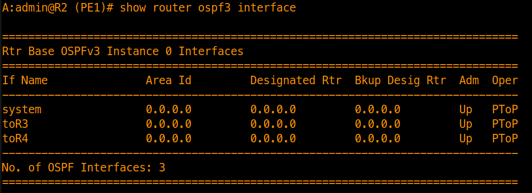
Inspect interface parameters on toR3:
/show router ospf3 interface "toR3" detail
[!NOTE] OSPFv3 vs. OSPFv2 Interface Identification: Unlike OSPFv2 which relies on IPv4 subnet addressing, OSPFv3 identifies interfaces using a 32-bit Interface ID and communicates over the interface’s IPv6 Link-Local Address (
fe80::/10). Thedetailcommand confirms the locally generated Link-Local address and the configured MTU.
A:admin@R2 (PE1)# /show router ospf3 interface "toR3" detail

===============================================================================
Rtr Base OSPFv3 Instance 0 Interface "toR3" (detail)
===============================================================================
-------------------------------------------------------------------------------
Configuration
-------------------------------------------------------------------------------
IP Address       : fe80::1ece:1ff:fe00:0-"toR3"
Area Id          : 0.0.0.0              Priority         : 1
Hello Intrvl     : 10 sec               Rtr Dead Intrvl  : 40 sec
Retrans Intrvl   : 5 sec                Poll Intrvl      : 120 sec
Cfg Metric       : 0                    Advert Subnet    : True
Transit Delay    : 1                    Cfg IF Type      : Point To Point
Passive          : False                Cfg MTU          : 0
LSA-filter-out   : None                 Adv Rtr Capab    : Yes
LFA              : Include              LFA NH Template  :
Load Bal Weight  : None                 Bfd Enabled      : No
Bfd Strict Mode  : No                   Bfd Str Holddown : 0 sec
RIB-priority     : None
IPsec InStatSA   :                      IPsec OutStatSA  :
IPsec InStatSATmp:
-------------------------------------------------------------------------------
2. Checking Adjacency States Across the Diamond Core
Verify that OSPFv3 forms full adjacencies across both branches of the core without DR/BDR election overhead:
/show router ospf3 neighbor
- Expected Core Adjacencies:
- R2 (PE1): 2 full neighbors → R3 (P1) and R4 (P2)
- R3 (P1): 2 full neighbors → R2 (PE1) and R5 (PE2)
- R4 (P2): 2 full neighbors → R2 (PE1) and R5 (PE2)
- R5 (PE2): 2 full neighbors → R3 (P1) and R4 (P2)
A:admin@R2 (PE1)# /show router ospf3 neighbor

===============================================================================
Rtr Base OSPFv3 Instance 0 Neighbors
===============================================================================
Interface-Name                   Rtr Id          State      Pri  RetxQ   TTL
   Area-Id
-------------------------------------------------------------------------------
toR3                             10.100.1.3      Full       1    0       30
   0.0.0.0
toR4                             10.100.1.4      Full       1    0       30
   0.0.0.0
-------------------------------------------------------------------------------
No. of Neighbors: 2
===============================================================================
Inspect neighbor details on R2 (PE1):
/show router ospf3 neighbor "toR3" detail
[!TIP] The Dual-Identity Feature of OSPFv3: The neighbor is identified by its 32-bit dotted-decimal Router ID (
10.100.1.3for R3), but the Neighbor IP used for peering and SPF next-hop calculations is R3’s Link-Local address (fe80::...), not its global unicast address.
[!IMPORTANT] 32-Bit Router ID Selection in Greenfield IPv6 Networks: OSPFv3 strictly retains a 32-bit dotted-decimal Router ID (RFC 5340), never a 128-bit IPv6 address. In our brownfield environment, SR OS automatically selected
10.100.1.3from R3’s active IPv4systeminterface. In a pure greenfield IPv6 lab without IPv4 addresses, SR OS cannot derive a Router ID dynamically and OSPFv3 will fail to start. In greenfield deployments, explicitly set the router ID before committing:/configure router router-id 10.100.1.x # or directly under the protocol context: /configure router ospf3 0 router-id 10.100.1.x
A:admin@R2 (PE1)# /show router ospf3 neighbor toR3 detail

===============================================================================
Rtr Base OSPFv3 Instance 0 Neighbors for Interface "toR3" (detail)
===============================================================================
-------------------------------------------------------------------------------
Neighbor : fe80::1ee9:2ff:fe00:0-"toR3"
-------------------------------------------------------------------------------
-------------------------------------------------------------------------------
Neighbor Rtr Id : 10.100.1.3  Interface: toR3
-------------------------------------------------------------------------------
Neighbor IP Addr : fe80::1ee9:2ff:fe00:0-"toR3"
Local IF IP Addr : fe80::1ece:1ff:fe00:0-"toR3"
Area Id          : 0.0.0.0
Designated Rtr   : 0.0.0.0              Backup Desig Rtr : 0.0.0.0
Neighbor State   : Full                 Priority         : 1
Retrans Q Length : 0                    Options          : -----R--EV6
Events           : 4                    Last Event Time  : 10/05/2025 19:43:39
Up Time          : 0d 00:15:57          Time Before Dead : 33 sec
GR Helper        : Not Helping          GR Helper Age    : 0 sec
GR Exit Reason   : None                 GR Restart Reason: Unknown (0)
BFD Strict Mode  : Disabled
Bad Nbr States   : 0                    LSA Inst fails   : 0
Bad Seq Nums     : 0                    Bad MTUs         : 0
Bad Packets      : 0                    LSA not in LSDB  : 0
Option Mismatches: 0                    Nbr Duplicates   : 0
Num Restarts     : 0                    Last Restart at  : Never
===============================================================================
3. Validating the IPv6 Routing Table & Core ECMP
Verify that remote loopbacks and transit subnets are learned dynamically across Area 0:
/show router route-table ipv6 protocol ospf3
Confirm that R3 (fd50:2026::3/128), R4 (fd50:2026::4/128), R5 (fd50:2026::5/128), and the remote transit subnets (fd50:2026:35::/64, fd50:2026:45::/64) are installed with protocol OSPF3:
A:admin@R2 (PE1)# /show router route-table ipv6 protocol ospf3

===============================================================================
IPv6 Route Table (Router: Base)
===============================================================================
Dest Prefix[Flags]                            Type    Proto     Age        Pref
      Next Hop[Interface Name]                                    Metric
-------------------------------------------------------------------------------
fd50:2026::3/128                              Remote  OSPF3     00h01m05s  10
       fe80::1e55:2ff:fe00:0-"toR3"                                 1
fd50:2026::4/128                              Remote  OSPF3     00h03m46s  10
       fe80::1edc:3ff:fe00:0-"toR4"                                 1
fd50:2026::5/128                              Remote  OSPF3     00h01m00s  10
       fe80::1e55:2ff:fe00:0-"toR3"                                 2
fd50:2026::5/128                              Remote  OSPF3     00h01m00s  10
       fe80::1edc:3ff:fe00:0-"toR4"                                 2
fd50:2026:35::/64                             Remote  OSPF3     00h01m00s  10
       fe80::1e55:2ff:fe00:0-"toR3"                                 2
fd50:2026:45::/64                             Remote  OSPF3     00h03m46s  10
       fe80::1edc:3ff:fe00:0-"toR4"                                 2
-------------------------------------------------------------------------------
No. of Routes: 6
Flags: n = Number of times nexthop is repeated
       B = BGP backup route available
       L = LFA nexthop available
       S = Sticky ECMP requested
===============================================================================
Verifying Equal-Cost Multi-Path (ECMP) to R5
Because R2 connects to R5 through two symmetrical paths (via R3 and via R4), inspect the prefix fd50:2026::5/128:
/show router route-table ipv6 fd50:2026::5/128
The output displays two distinct next-hops (the Link-Local addresses of R3 and R4 over toR3 and toR4), confirming ECMP load balancing across Area 0:
A:admin@R2 (PE1)# /show router route-table ipv6 fd50:2026::5/128

===============================================================================
IPv6 Route Table (Router: Base)
===============================================================================
Dest Prefix[Flags]                            Type    Proto     Age        Pref
      Next Hop[Interface Name]                                    Metric
-------------------------------------------------------------------------------
fd50:2026::5/128                              Remote  OSPF3     00h02m16s  10
       fe80::1e55:2ff:fe00:0-"toR3"                                 2
fd50:2026::5/128                              Remote  OSPF3     00h02m16s  10
       fe80::1edc:3ff:fe00:0-"toR4"                                 2
-------------------------------------------------------------------------------
No. of Routes: 2
Flags: n = Number of times nexthop is repeated
       B = BGP backup route available
       L = LFA nexthop available
       S = Sticky ECMP requested
===============================================================================
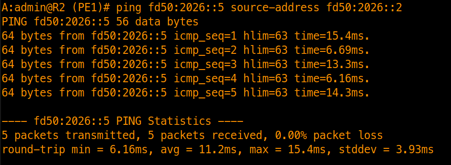
Data Plane Reachability Test
Validate data plane reachability across Area 0 by pinging R5’s loopback from R2’s loopback:
ping fd50:2026::5 source-address fd50:2026::2
4. Link-State Database (LSDB) Analysis: Decoupling of Topology from Addresses
In OSPFv2, Type 1 Router LSAs advertised both router links and IPv4 subnet prefixes. In OSPFv3, topology is strictly decoupled from addressing.
Step A: Compare Area 0 LSDB Across P and PE Nodes
Verify that PE1 (R2) and P1 (R3) maintain identical copies of the Area 0 database:
/show router ospf3 database
A:admin@R2 (PE1)# /show router ospf3 database

===============================================================================
Rtr Base OSPFv3 Instance 0 Link State Database (type: All)
===============================================================================
Type    Area Id         Link State Id   Adv Rtr Id      Age  Sequence   Cksum
-------------------------------------------------------------------------------
Router  0.0.0.0         0.0.0.0         10.100.1.2      683  0x80000009 0x7031
Router  0.0.0.0         0.0.0.0         10.100.1.3      685  0x80000007 0x6c37
Router  0.0.0.0         0.0.0.0         10.100.1.4      684  0x80000004 0xa003
Router  0.0.0.0         0.0.0.0         10.100.1.5      686  0x80000006 0x6c35
IA Pfx  0.0.0.0         0.0.0.0         10.100.1.2      692  0x80000008 0x2bc3
IA Pfx  0.0.0.0         0.0.0.0         10.100.1.3      685  0x80000009 0xfca
IA Pfx  0.0.0.0         0.0.0.0         10.100.1.4      684  0x80000006 0xeed9
IA Pfx  0.0.0.0         0.0.0.0         10.100.1.5      691  0x80000006 0x8ac
-------------------------------------------------------------------------------
No. of LSAs: 8
===============================================================================
A:admin@R3 (P1)# /show router ospf3 database

===============================================================================
Rtr Base OSPFv3 Instance 0 Link State Database (type: All)
===============================================================================
Type    Area Id         Link State Id   Adv Rtr Id      Age  Sequence   Cksum
-------------------------------------------------------------------------------
Router  0.0.0.0         0.0.0.0         10.100.1.2      810  0x80000009 0x7031
Router  0.0.0.0         0.0.0.0         10.100.1.3      810  0x80000007 0x6c37
Router  0.0.0.0         0.0.0.0         10.100.1.4      810  0x80000004 0xa003
Router  0.0.0.0         0.0.0.0         10.100.1.5      811  0x80000006 0x6c35
IA Pfx  0.0.0.0         0.0.0.0         10.100.1.2      819  0x80000008 0x2bc3
IA Pfx  0.0.0.0         0.0.0.0         10.100.1.3      810  0x80000009 0xfca
IA Pfx  0.0.0.0         0.0.0.0         10.100.1.4      810  0x80000006 0xeed9
IA Pfx  0.0.0.0         0.0.0.0         10.100.1.5      816  0x80000006 0x8ac
-------------------------------------------------------------------------------
No. of LSAs: 8
===============================================================================
The database summary on both routers confirms:
- Router LSAs (
0x2001): 4 entries (10.100.1.2,10.100.1.3,10.100.1.4,10.100.1.5) representing router adjacency topology without prefix information. - Intra-Area-Prefix LSAs (
IA Pfx/0x2009): 4 entries carrying the IPv6 prefix reachability for each node.
Step B: Inspect the Router LSA (Type 1 / Topology Only)
Inspect R3’s Router LSA on R2:
/show router ospf3 database type router detail
A:admin@R2 (PE1)# /show router ospf3 database type router detail

===============================================================================
Rtr Base OSPFv3 Instance 0 Link State Database (type: Router) (detail)
===============================================================================
-------------------------------------------------------------------------------
Router LSA for Area 0.0.0.0
-------------------------------------------------------------------------------
Area Id          : 0.0.0.0              Adv Router Id    : 10.100.1.3
Link State Id    : 0.0.0.0 (0)
LSA Type         : Router
Sequence No      : 0x80000007           Checksum         : 0x6c37
Age              : 1005                 Length           : 56
Options          : -----R--EV6
Flags            :                      Link Count       : 2
Link Type (1)    : P2P Link             Nbr Rtr ID (1)   : 10.100.1.2
I/F Index (1)    : 2                    Nbr I/F Index (1): 4
Metric (1)       : 1
Link Type (2)    : P2P Link             Nbr Rtr ID (2)   : 10.100.1.5
I/F Index (2)    : 3                    Nbr I/F Index (2): 3
Metric (2)       : 1
-------------------------------------------------------------------------------
- Observation: The Router LSA contains point-to-point link descriptions, neighbor Router IDs, and Interface IDs, but zero IPv6 prefix addresses. A link flapping an IP address does not trigger a full Dijkstra SPF calculation for the entire area.
Step C: Inspect the Intra-Area-Prefix LSA (Type 9 / Prefix Carrier)
Inspect where IPv6 loopback and transit prefixes are advertised:
/show router ospf3 database type intra-area-pfx detail
A:admin@R2 (PE1)# /show router ospf3 database type intra-area-pfx detail

===============================================================================
Rtr Base OSPFv3 Instance 0 Link State Database (type: IA Pfx) (detail)
===============================================================================
-------------------------------------------------------------------------------
IA Pfx LSA for Area 0.0.0.0
-------------------------------------------------------------------------------
Area Id          : 0.0.0.0              Adv Router Id    : 10.100.1.2
Link State Id    : 0.0.0.0 (0)
LSA Type         : IA Pfx
Sequence No      : 0x8000000a           Checksum         : 0x27c5
Age              : 340                  Length           : 76
Ref Ls Type      : 2001                 Ref Ls Id        : 0
Ref Adv Rtr      : 10.100.1.2           No of Pfxs       : 3
Prefix (1)       : fd50:2026::2/128
Pfx Options (1)  : LA                   Metric (1)       : 0
Prefix (2)       : fd50:2026:23::/64
Pfx Options (2)  :                      Metric (2)       : 1
Prefix (3)       : fd50:2026:24::/64
Pfx Options (3)  :                      Metric (3)       : 1
-------------------------------------------------------------------------------
IA Pfx LSA for Area 0.0.0.0
-------------------------------------------------------------------------------
Area Id          : 0.0.0.0              Adv Router Id    : 10.100.1.3
Link State Id    : 0.0.0.0 (0)
LSA Type         : IA Pfx
Sequence No      : 0x8000000b           Checksum         : 0xbcc
Age              : 328                  Length           : 76
...
- Observation: This LSA explicitly references the Router LSA (
Ref Ls Type: 2001) and lists the IPv6 prefixes (fd50:2026::X/128and transit/64subnets) associated with that router.
Step D: Inspect the Link LSA (Type 8 / Link-Local Scope)
Because Link LSAs (Type 8 / 0x0008) are scoped per-link and not flooded across the entire area, view them under the interface hierarchy:
/show router ospf3 interface "toR3" database detail
A:admin@R2 (PE1)# /show router ospf3 interface "toR3" database detail

===============================================================================
Rtr Base OSPFv3 Instance 0 Link State Database (detail)
===============================================================================
-------------------------------------------------------------------------------
Link LSA
-------------------------------------------------------------------------------
Interface Address: 192.168.23.1         Adv Router Id    : 10.100.1.2
Link State Id    : 0.0.0.4              LSA Type         : Link
Sequence No      : 0x80000002           Checksum         : 0x2d99
Age              : 1365                 Length           : 56
Options          : -----R--EV6          Rtr Priority     : 1
Link Local Addr  : fe80::1e56:1ff:fe00:0
No of Pfxs       : 1
Prefix (1)       : fd50:2026:23::/64
Pfx Options (1)  :
-------------------------------------------------------------------------------
Link LSA
-------------------------------------------------------------------------------
Interface Address: 192.168.23.1         Adv Router Id    : 10.100.1.3
Link State Id    : 0.0.0.2              LSA Type         : Link
Sequence No      : 0x80000004           Checksum         : 0x388d
Age              : 253                  Length           : 56
Options          : -----R--EV6          Rtr Priority     : 1
Link Local Addr  : fe80::1e55:2ff:fe00:0
No of Pfxs       : 1
Prefix (1)       : fd50:2026:23::/64
Pfx Options (1)  :
===============================================================================
- Observation: The Link LSA informs the adjacent neighbor of the router’s link-local address (
fe80::...) on that interface and lists the IPv6 global prefixes configured on the link.
Configuring Multi-Area OSPFv3
With Area 0 established, scale the topology by adding dedicated edge areas: Area 1 connecting R1 (CE1) to R2 (PE1), and Area 2 connecting R6 (CE2) to R5 (PE2).
Configuring Non-Backbone Areas
Configure Area 1 (R1 and R2)
- On Router R1 (CE1):
edit-config global
/configure router interface "system" ipv6 address fd50:2026::1 prefix-length 128
/configure router interface "toR2" ipv6 address fd50:2026:12::1 prefix-length 64

/configure router ospf3 0 admin-state enable
/configure router ospf3 0 area 1 interface "system" interface-type point-to-point passive true
/configure router ospf3 0 area 1 interface "toR2" interface-type point-to-point
commit
- On Router R2 (PE1 - ABR mapping interface to Area 1):
edit-config global
/configure router interface "toR1" ipv6 address fd50:2026:12::2 prefix-length 64
/configure router ospf3 0 area 1 interface "toR1" interface-type point-to-point
commit
Configure Area 2 (R5 and R6)
- On Router R6 (CE2):
edit-config global
/configure router interface "system" ipv6 address fd50:2026::6 prefix-length 128
/configure router interface "toR5" ipv6 address fd50:2026:56::2 prefix-length 64

/configure router ospf3 0 admin-state enable
/configure router ospf3 0 area 2 interface "system" interface-type point-to-point passive true
/configure router ospf3 0 area 2 interface "toR5" interface-type point-to-point
commit
- On Router R5 (PE2 - ABR mapping interface to Area 2):
edit-config global
/configure router interface "toR6" ipv6 address fd50:2026:56::1 prefix-length 64
/configure router ospf3 0 area 2 interface "toR6" interface-type point-to-point
commit
Verification & Multi-Area Protocol Inspection
Verify ABR boundary roles, Inter-Area Prefix LSA propagation, cumulative path metrics, and end-to-end data plane reachability.
1. Validating ABR Status on Provider Edge Routers
Verify that PE routers recognize their boundary roles:
/show router ospf3 status
Confirm on R2 (PE1) and R5 (PE2):
Area Border Router : True- Active areas reflect multi-area topology (Area 0 and Area 1 on R2; Area 0 and Area 2 on R5).
A:admin@R2 (PE1)# /show router ospf3 status

===============================================================================
Rtr Base OSPFv3 Instance 0 Status
===============================================================================
OSPF Cfg Router Id           : 0.0.0.0
OSPF Oper Router Id          : 10.100.1.2
OSPF Version                 : 3
OSPF Admin Status            : Enabled
OSPF Oper Status             : Enabled
Graceful Restart             : Disabled
GR Helper Mode               : Disabled
GR Strict LSA Checking       : Enabled (operational down)
Preference                   : 10
External Preference          : 150
Backbone Router              : True
Area Border Router           : True
AS Border Router             : False
[!NOTE] An ABR automatically activates generation of Inter-Area-Prefix LSAs (Type 3 /
0x2003), displayed asIE Pfxin SR OS, to leak reachability between connected areas and Area 0.
2. Multi-Area LSDB Inspection on Customer Edge (R1 - CE1)
Log into R1 (CE1) in Area 1 to observe how the ABR isolates topology while advertising remote reachability.
Step A: General Database Summary
/show router ospf3 database
A:admin@R1 (CE1)# /show router ospf3 database

===============================================================================
Rtr Base OSPFv3 Instance 0 Link State Database (type: All)
===============================================================================
Type    Area Id         Link State Id   Adv Rtr Id      Age  Sequence   Cksum
-------------------------------------------------------------------------------
Router  0.0.0.1         0.0.0.0         10.100.1.1      307  0x80000002 0x35fe
Router  0.0.0.1         0.0.0.0         10.100.1.2      308  0x80000002 0x280b
IE Pfx  0.0.0.1         0.0.0.1         10.100.1.2      291  0x80000005 0x425f
IE Pfx  0.0.0.1         0.0.0.2         10.100.1.2      302  0x80000001 0x7258
IE Pfx  0.0.0.1         0.0.0.3         10.100.1.2      302  0x80000001 0x7850
IE Pfx  0.0.0.1         0.0.0.4         10.100.1.2      291  0x80000001 0x6639
IE Pfx  0.0.0.1         0.0.0.5         10.100.1.2      289  0x80000001 0x7c28
IE Pfx  0.0.0.1         0.0.0.6         10.100.1.2      285  0x80000001 0x9207
IE Pfx  0.0.0.1         0.0.0.7         10.100.1.2      285  0x80000001 0x6832
IE Pfx  0.0.0.1         0.0.0.8         10.100.1.2      285  0x80000001 0x634d
IE Pfx  0.0.0.1         0.0.0.9         10.100.1.2      285  0x80000001 0x6b23
IA Pfx  0.0.0.1         0.0.0.0         10.100.1.1      307  0x80000005 0x7993
IA Pfx  0.0.0.1         0.0.0.0         10.100.1.2      307  0x80000003 0x67d2
-------------------------------------------------------------------------------
No. of LSAs: 13
===============================================================================
- Key Observations:
- Router LSAs (
0x2001): Only two entries exist—R1 (10.100.1.1) and R2 (10.100.1.2). R1 has no visibility into the core routers (R3, R4, R5) or remote CE (R6) at the link-state level, preventing Area 1 SPF recomputations during core topology changes. - Intra-Area-Prefix LSAs (
IA Pfx/0x2009): Contain only local Area 1 prefixes (R1 loopbackfd50:2026::1/128and transit linkfd50:2026:12::/64). - Inter-Area-Prefix LSAs (
IE Pfx/0x2003): Exactly 9 entries injected by ABR R2 (10.100.1.2), advertising all remote subnets across Area 0 and Area 2:- 4 Remote System Loopbacks:
fd50:2026::2/128(R2),fd50:2026::4/128(R4),fd50:2026::5/128(R5), andfd50:2026::6/128(R6). (Note: In this test capture, R3’s system loopback was not advertised, leaving 4 loopbacks). - 5 Remote Transit Subnets:
fd50:2026:23::/64(R2–R3),fd50:2026:24::/64(R2–R4),fd50:2026:35::/64(R3–R5),fd50:2026:45::/64(R4–R5), andfd50:2026:56::/64(R5–R6). (Local linkfd50:2026:12::/64remains intra-area).
- 4 Remote System Loopbacks:
- Router LSAs (
Step B: Detailed Inter-Area-Prefix LSA Inspection
Inspect the LSA representing remote CE2’s loopback (fd50:2026::6/128):
/show router ospf3 database type inter-area-pfx detail
A:admin@R1 (CE1)# /show router ospf3 database type inter-area-pfx detail

===============================================================================
Rtr Base OSPFv3 Instance 0 Link State Database (type: IE Pfx) (detail)
===============================================================================
.
.
.
-------------------------------------------------------------------------------
IE Pfx LSA for Area 0.0.0.1
-------------------------------------------------------------------------------
Area Id          : 0.0.0.1              Adv Router Id    : 10.100.1.2
Link State Id    : 0.0.0.6 (6)
LSA Type         : IE Pfx
Sequence No      : 0x80000001           Checksum         : 0x9207
Age              : 845                  Length           : 44
Pfx Options      :                      Metric           : 3
Dest Prefix      : fd50:2026::6/128
-------------------------------------------------------------------------------
- Parameters Inspected:
- LSA Type:
IE Pfx(Inter-Area-Prefix LSA /0x2003). - Advertising Router:
10.100.1.2(ABR R2). - Dest Prefix:
fd50:2026::6/128(CE2 Loopback). - Metric: Displays a cost of
3calculated by R2 across Area 0 to reach R6 prior to injection into Area 1.
- LSA Type:
3. Verifying Route Table & Accumulated Path Costs
Verify that the IPv6 routing table installs inter-area routes with their accumulated path costs:
/show router route-table ipv6 protocol ospf3
A:admin@R1 (CE1)# /show router route-table ipv6 protocol ospf3

===============================================================================
IPv6 Route Table (Router: Base)
===============================================================================
Dest Prefix[Flags]                            Type    Proto     Age        Pref
      Next Hop[Interface Name]                                    Metric
-------------------------------------------------------------------------------
fd50:2026::2/128                              Remote  OSPF3     00h24m22s  10
       fe80::1e65:1ff:fe00:0-"toR2"                                 1
fd50:2026::4/128                              Remote  OSPF3     00h24m11s  10
       fe80::1e65:1ff:fe00:0-"toR2"                                 2
fd50:2026::5/128                              Remote  OSPF3     00h24m05s  10
       fe80::1e65:1ff:fe00:0-"toR2"                                 3
fd50:2026::6/128                              Remote  OSPF3     00h24m05s  10
       fe80::1e65:1ff:fe00:0-"toR2"                                 4
fd50:2026:23::/64                             Remote  OSPF3     00h24m22s  10
       fe80::1e65:1ff:fe00:0-"toR2"                                 2
fd50:2026:24::/64                             Remote  OSPF3     00h24m22s  10
       fe80::1e65:1ff:fe00:0-"toR2"                                 2
fd50:2026:35::/64                             Remote  OSPF3     00h24m05s  10
       fe80::1e65:1ff:fe00:0-"toR2"                                 4
fd50:2026:45::/64                             Remote  OSPF3     00h24m09s  10
       fe80::1e65:1ff:fe00:0-"toR2"                                 3
fd50:2026:56::/64                             Remote  OSPF3     00h24m05s  10
       fe80::1e65:1ff:fe00:0-"toR2"                                 4
-------------------------------------------------------------------------------
No. of Routes: 9
Flags: n = Number of times nexthop is repeated
       B = BGP backup route available
       L = LFA nexthop available
       S = Sticky ECMP requested
===============================================================================
Query the specific route for CE2’s system loopback (fd50:2026::6/128):
/show router route-table ipv6 fd50:2026::6/128
A:admin@R1 (CE1)# /show router route-table ipv6 fd50:2026::6/128

===============================================================================
IPv6 Route Table (Router: Base)
===============================================================================
Dest Prefix[Flags]                            Type    Proto     Age        Pref
      Next Hop[Interface Name]                                    Metric
-------------------------------------------------------------------------------
fd50:2026::6/128                              Remote  OSPF3     00h27m41s  10
       fe80::1e65:1ff:fe00:0-"toR2"                                 4
-------------------------------------------------------------------------------
No. of Routes: 1
Flags: n = Number of times nexthop is repeated
       B = BGP backup route available
       L = LFA nexthop available
       S = Sticky ECMP requested
===============================================================================
Understanding the Accumulated Metric
The total cost to fd50:2026::6/128 on R1 is calculated as:
Cost = Cost(R1→R2) + Cost(R2→R3/R4) + Cost(R3/R4→R5) + Cost(R5→R6)
With default link metrics of 1 per hop:
- 1 (Area 1 link) + 1 (Area 0 hop) + 1 (Area 0 hop) + 1 (Area 2 link) = 4.
[!TIP] Next-Hop Verification: Although destination
fd50:2026::6/128is located across multiple areas, the Next-Hop installed in R1’s forwarding table is the Link-Local address (fe80::...) of R2 on interfacetoR2.
4. End-to-End Data Plane Reachability & Path Trace
Validate data plane reachability across the multi-area topology.
Sourced Loopback-to-Loopback Ping
Execute an end-to-end ping from R1 (CE1) to R6 (CE2), explicitly sourcing from R1’s system loopback:
ping fd50:2026::6 source-address fd50:2026::1
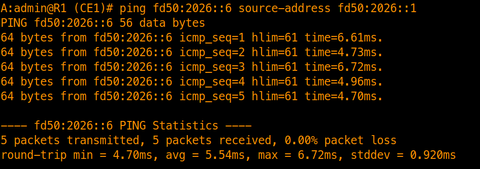
Sourcing from fd50:2026::1 verifies bidirectional host-to-host transit across all area boundaries (Area 1 → Area 0 → Area 2) and back.
Tracing the Multi-Area Path
Trace the routed path across all six nodes:
traceroute fd50:2026::6 source-address fd50:2026::1

- Hop Progression:
fd50:2026:12::2(R2 - PE1 Ingress ABR)fd50:2026:24::2(R4 - P2 Core Router, traversing the lower branch of the core)fd50:2026:45::2(R5 - PE2 Egress ABR)fd50:2026::6(R6 - CE2 Remote Destination)
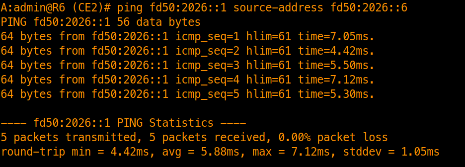
Bidirectional Verification
From R6 (CE2), execute the reverse test back to R1:
ping fd50:2026::1 source-address fd50:2026::6
Series Conclusion: The Complete OSPF Journey on Nokia SR OS
This post concludes our 5-part deep dive into OSPF architecture and implementation on Nokia SR OS:
- Part 1: Physical Foundation & Chassis Provisioning: Established the hardware foundation, card/MDA/port provisioning, hybrid ethernet modes, and IP interface bindings.
- Part 2: Single-Area OSPFv2 Baseline: Configured Area 0 across the diamond core, evaluated Point-to-Point vs. Broadcast network types, and observed DR/BDR election mechanics.
- Part 3: Multi-Area OSPFv2 & Boundary Hierarchy: Segmented edge networks into Area 1 and Area 2, implemented external route redistribution on ASBRs, and compared Stub, Totally Stubby, NSSA, and Totally NSSA database filtering.
- Part 4: Route Summarization, Metric Tuning, ECMP & IP FRR: Hardened the routing domain using inter-area and external prefix summarization, reference bandwidth metric tuning, ECMP, Loop-Free Alternate (LFA), and sub-second hardware IP Fast Reroute.
- Part 5: OSPFv3 IPv6 Routing & LSDB Decoupling: Migrated to native IPv6 routing, established peering over Link-Local addresses, and analyzed the complete separation of topology from IP prefix reachability via Type 8 Link and Type 9 Intra-Area-Prefix LSAs.
With our OSPF foundation complete, the next series explores IS-IS on Nokia SR OS, covering its TLV-based architecture, multi-protocol operation, and implementation in service provider networks.