
Building on the single-area baseline from Part 2, this post covers segmentation of the network into multiple OSPF areas, introduces Autonomous System Boundary Routers (ASBRs) for external route redistribution, and covers Stub, Totally Stubby, NSSA, and Totally NSSA area types with LSDB analysis at each stage.
- SR OS Version: 25.7.R1
- CLI Mode: MD-CLI (Model-Driven CLI)
Multi-Area Configuration
To transition into a multi-area design, we use R2 (PE1) and R5 (PE2) as our Area Border Routers (ABRs) to connect their respective edge customer networks to the Area 0 backbone:
- Area 1: R1 (CE1) connects to R2 (PE1)
- Area 0 (Backbone): R2 (PE1), R3 (P1), R4 (P2), and R5 (PE2)
- Area 2: R6 (CE2) connects to R5 (PE2)
Node Configurations (R1-R6)
Router R1 (CE1) - Move to Area 1
On R1, remove Area 0 and place its interfaces into Area 1:
/configure router ospf 0 delete area 0
/configure router ospf 0 area 1 interface "system" interface-type point-to-point
/configure router ospf 0 area 1 interface "system" passive true
/configure router ospf 0 area 1 interface "toR2" interface-type point-to-point
/configure router ospf 0 area 1 interface "toR2" authentication-type message-digest
/configure router ospf 0 area 1 interface "toR2" message-digest-key 1 md5 NokiaOSPF2026

commit
Router R2 (PE1) - ABR Configuration (Area 0 & Area 1)
On R2, keep core transit links in Area 0, but reassign the link facing R1 into Area 1:
/configure router ospf 0 area 0 delete interface "toR1"
/configure router ospf 0 area 1 interface "toR1" interface-type point-to-point
/configure router ospf 0 area 1 interface "toR1" authentication-type message-digest
/configure router ospf 0 area 1 interface "toR1" message-digest-key 1 md5 NokiaOSPF2026

commit
Routers R3 (P1) & R4 (P2) - Remain in Area 0
R3 and R4 remain entirely inside the Area 0 backbone. No configuration changes are required for them.
Router R5 (PE2) - ABR Configuration (Area 0 & Area 2)
On R5, keep core transit links in Area 0, but reassign the link facing R6 into Area 2:
/configure router ospf 0 area 0 delete interface "toR6"
/configure router ospf 0 area 2 interface "toR6" interface-type point-to-point
/configure router ospf 0 area 2 interface "toR6" authentication-type message-digest
/configure router ospf 0 area 2 interface "toR6" message-digest-key 1 md5 NokiaOSPF2026

commit
Router R6 (CE2) - Move to Area 2
On R6, remove Area 0 and place its interfaces into Area 2:
/configure router ospf 0 delete area 0
/configure router ospf 0 area 2 interface "system" interface-type point-to-point
/configure router ospf 0 area 2 interface "system" passive true
/configure router ospf 0 area 2 interface "toR5" interface-type point-to-point
/configure router ospf 0 area 2 interface "toR5" authentication-type message-digest
/configure router ospf 0 area 2 interface "toR5" message-digest-key 1 md5 NokiaOSPF2026

commit
Multi-Area Verification
Verify that adjacencies have formed and the LSDB reflects the new area assignments:
Verify Adjacencies on R1 (CE1)
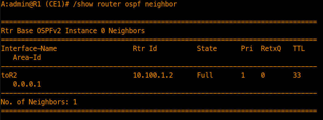
Confirm that R2 appears in a Full state within Area 1.
Inspect the LSDB on R1 (CE1)
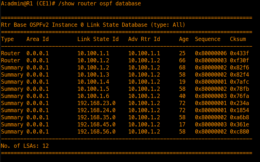
Verify that the LSDB contains local Router LSAs (Type 1) alongside Network Summary LSAs (Type 3) injected by ABR R2 for the Area 0 core prefixes and Area 2 endpoints.
Inspect the LSDB on ABR R2 (PE1)
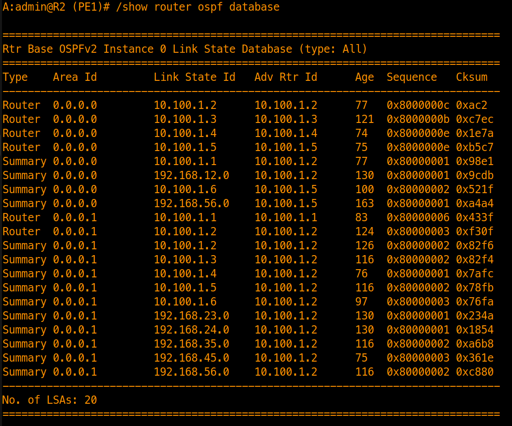
Verify that R2 maintains separate LSAs spanning both Area 0 and Area 1.
Advertising External Prefixes into OSPF
To inject prefixes external to our IGP domain, we enable Autonomous System Boundary Router (ASBR) capabilities on our PE nodes and configure export routing policies.
Step 1: Configure PE Routers as ASBRs and Create External Interfaces
Router R2 (PE1)
Enable ASBR and create a Loopback interface:
/configure router ospf 0 asbr
/configure router interface "loopback1" ipv4 primary address 192.168.100.2
/configure router interface "loopback1" ipv4 primary prefix-length 32
/configure router interface "loopback1" loopback

commit
Router R5 (PE2)
Enable ASBR and create a Loopback interface:
/configure router ospf 0 asbr
/configure router interface "loopback1" ipv4 primary address 192.168.200.5
/configure router interface "loopback1" ipv4 primary prefix-length 32
/configure router interface "loopback1" loopback

commit
Step 2: Define and Apply Export Routing Policies
Next, we create a prefix list matching our loopback IP addresses, configure the routing policy on our ABRs and apply it to OSPF to enable the PE routers to redistribute the loopback prefixes into OSPF.
Configure Prefix List and Policy Statement on R2
/configure policy-options prefix-list "external" prefix 192.168.100.2/32 type exact
/configure policy-options policy-statement "export-external" entry 10 from prefix-list ["external"]
/configure policy-options policy-statement "export-external" entry 10 from protocol name [direct]
/configure policy-options policy-statement "export-external" entry 10 action action-type accept

commit
Configure Prefix List and Policy Statement on R5
/configure policy-options prefix-list "external" prefix 192.168.200.5/32 type exact
/configure policy-options policy-statement "export-external" entry 10 from prefix-list ["external"]
/configure policy-options policy-statement "export-external" entry 10 from protocol name [direct]
/configure policy-options policy-statement "export-external" entry 10 action action-type accept

commit
Apply Export Policy to OSPF (R2 & R5)
/configure router ospf 0 export-policy "export-external"
commit
Step 3: Verify External Route Injection
Once the policies are active, verify the external routes from your CE routers (R1 or R6):
Check ASBR Summaries (Type 4 LSAs) & AS-External LSAs (Type 5)
Type 4 LSAs are generated by the ABRs to advertise the router ID of the ASBRs while Type 5 LSAs are generated by ASBRs to advertise external prefixes.
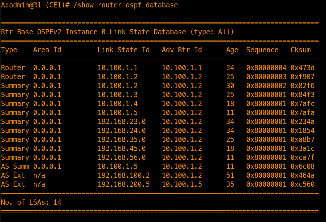
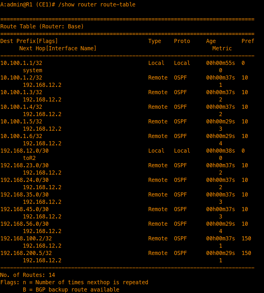
Inspect the metric and metric type associated with external prefixes
/show router route-table
/show router ospf database type external link-state-id 192.168.100.2 detail
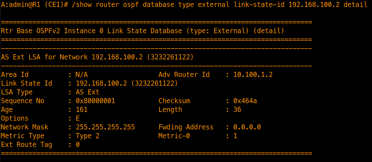
(By default, these routes appear as Type 2 external routes with a fixed seed metric of 1). Also, note the metric (150) associated with external prefixes.
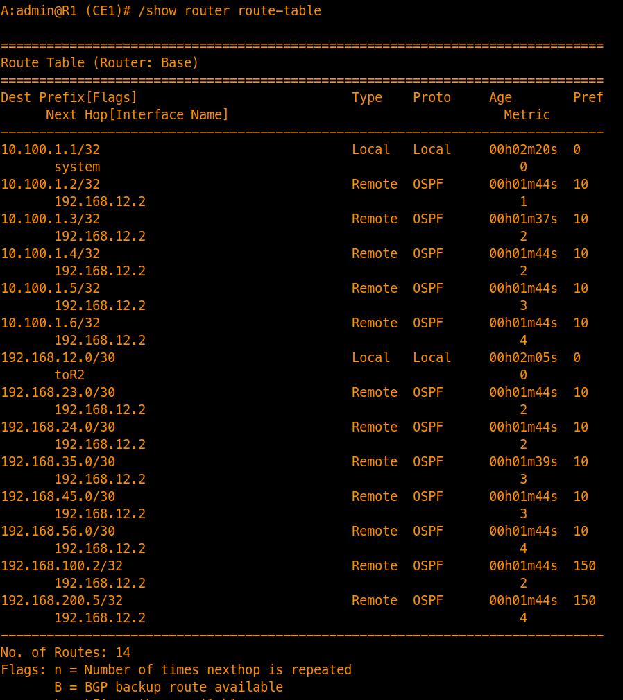
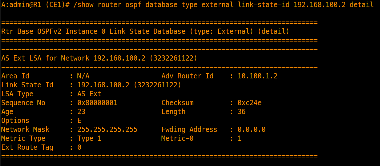
Switch to Type 1 Metrics (Optional / Recommended)
To factor in the internal cost across the core to reach the ASBR, update the policy action on R2 and R5:
/configure policy-options policy-statement "export-external" entry 10 action type 1
commit
Inspect the new metric and metric type associated with external prefixes
/show router route-table
/show router ospf database type external link-state-id 192.168.100.2 detail
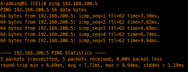
Verify Reachability
Configuring Stub Areas
To optimize our network and reduce LSDB overhead on edge routers, we convert our non-backbone areas (Area 1 and Area 2) into Stub Areas. This blocks AS-External LSAs (Type 5) and ASBR Summary LSAs (Type 4) from entering the stub area, replacing them with a default route (0.0.0.0/0) injected by the ABR.

Step 1: Apply Stub Configuration
To make an area a stub, apply the configuration on both the PE/ABR and CE routers sharing that non-backbone area.
Area 1 - R1 (CE1) & R2 (PE1)
/configure router ospf 0 area 1 stub
commit
Area 2 - R5 (PE2) & R6 (CE2)
/configure router ospf 0 area 2 stub
commit
Step 2: Stub Verification
After committing, OSPF adjacencies briefly reset and re-establish. Verify that Type 4 and Type 5 LSAs are stripped from the LSDB and replaced by a default route (0.0.0.0/0) injected by the ABR.
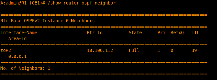
Check Neighbors
Verify that adjacencies are fully restored:
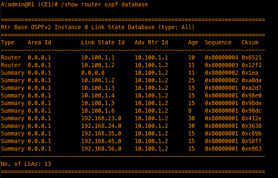
Inspect LSDB on R1 (CE1)
On a stub router (like R1 or R6), viewing the OSPF database will show that the AS External (Type 5) and ASBR Summary (Type 4) LSAs are gone. Instead, the ABR injects a Type 3 Network Summary LSA advertising the default route (0.0.0.0/0):
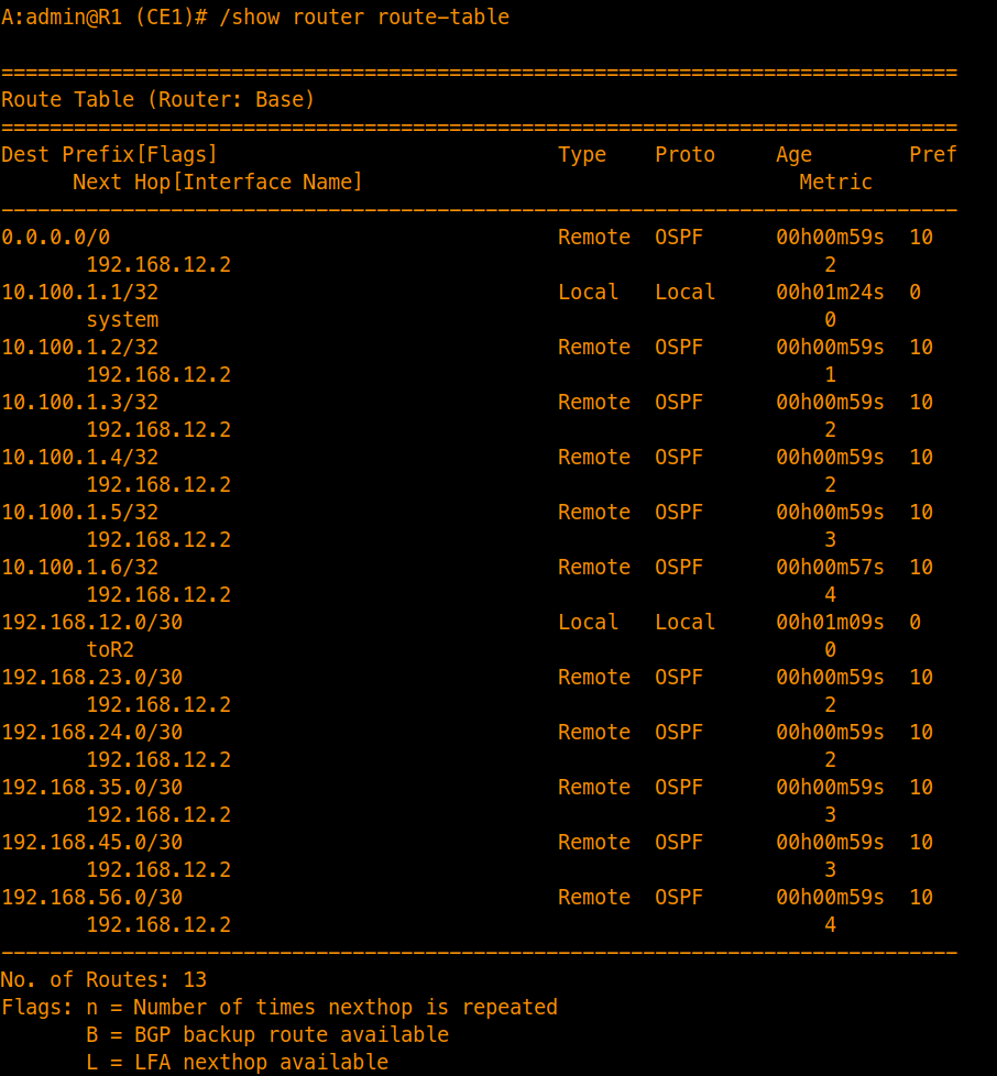
Verify Route Table on R1
Looking at the routing table on your CE router, individual external prefixes are now condensed into a single default route pointing toward the ABR:
Test Reachability
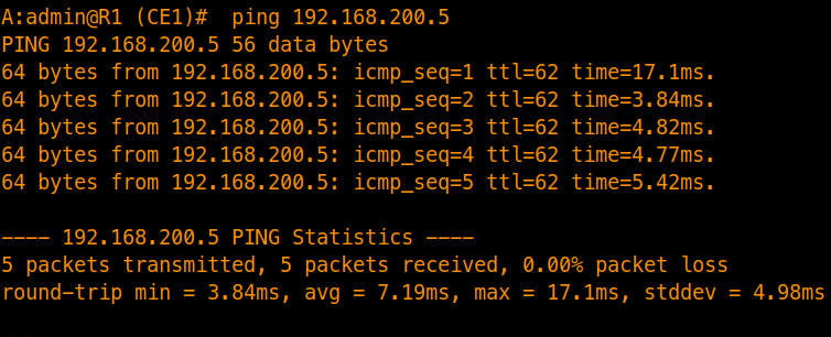
Test connectivity to the remote loopback (e.g., 192.168.200.5) from the stub router. Traffic is forwarded via the default route injected by the ABR — no specific external prefix is needed in the stub LSDB.
Configuring Totally Stubby Areas
We can further optimize stub areas by converting them into Totally Stubby Areas. By disabling summary advertisements on the ABR, inter-area prefixes (Type 3 Summary LSAs) are also blocked, leaving only the default route and local intra-area routes in the LSDB.

Step 1: Apply Totally Stubby Configuration on ABRs
Unlike standard stub areas, changes are only required on the PE/ABR routers (R2 for Area 1 and R5 for Area 2). The CE routers do not require any configuration changes.
On Router R2 (PE1) for Area 1
/configure router ospf 0 area 1 stub summaries false
commit
On Router R5 (PE2) for Area 2
/configure router ospf 0 area 2 stub summaries false
commit
Step 2: Totally Stubby Verification
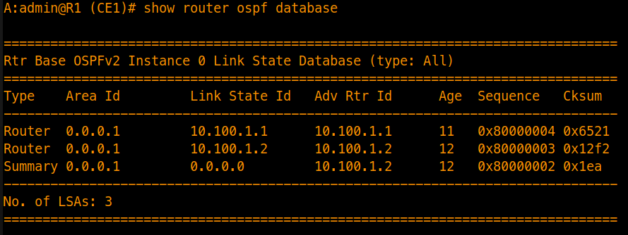
On R1 or R6, verify that the LSDB contains only the default route and local intra-area entries — all inter-area summaries, ASBR summaries, and AS-Externals are stripped.
Inspect LSDB on R1 (CE1)
You will notice that all Inter-Area Summary LSAs (except for the single default route 0.0.0.0/0), ASBR Summaries, and AS-Externals have been completely stripped from the database:
Review Routing Table on R1
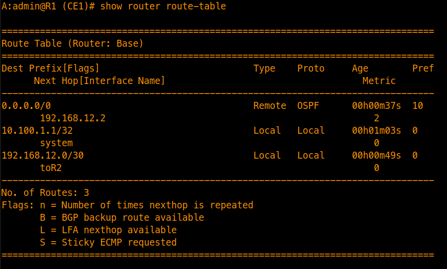
The CE router’s routing table is now heavily summarized, containing only its local interface subnets, local system addresses, and the default route (0.0.0.0/0) pointing to the ABR for all external and remote destinations:
Test Reachability
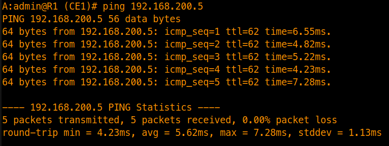
Ping 192.168.200.5 from R1 to confirm reachability. With no specific inter-area or external prefixes in the routing table, traffic is forwarded via the single default route pointing to the ABR.
Configuring Not-So-Stubby Areas (NSSA)
A Not-So-Stubby Area (NSSA) blocks external Type 5 LSAs coming from the backbone, but permits an internal router to act as an ASBR by injecting external prefixes using Type 7 LSAs. The ABR then translates these Type 7 LSAs into Type 5 LSAs before flooding them into Area 0.

Step 1: Apply NSSA Configuration
To convert Area 1 into an NSSA, apply the configuration command on both routers sharing the area (R1 and R2).
On Router R1 (CE1) & Router R2 (PE1) for Area 1
/configure router ospf 0 area 1 nssa
commit
Step 2: NSSA Verification
Once committed, check the link-state database on R1 or R2 to observe how external routes are handled within the NSSA.
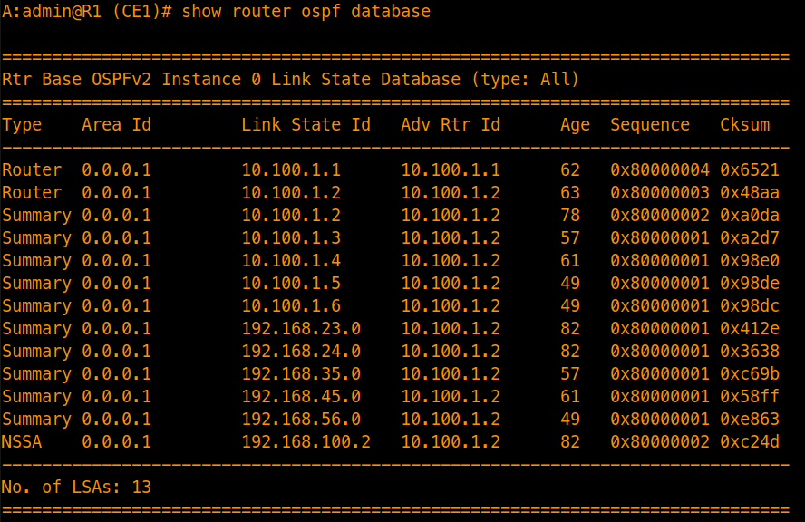
Inspect LSDB on R1 (CE1)
Instead of standard Type 5 AS-External LSAs, external routes originated inside or through the NSSA appear as NSSA (Type 7) LSAs:
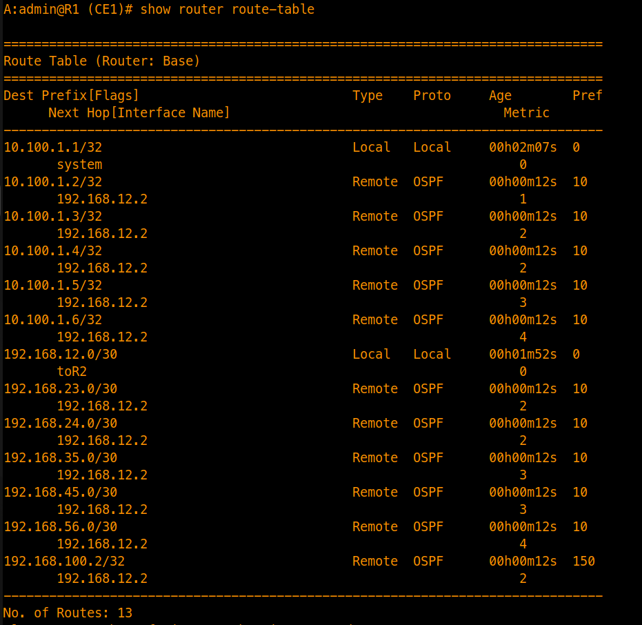
Verify Route Table on R1
Confirm that the external prefix learned via Type 7 LSA is installed in the routing table and reachable:
Configuring Totally Not-So-Stubby Areas (Totally NSSA)
A Totally NSSA takes NSSA a step further by blocking inter-area summary routes (Type 3 LSAs) on the ABR, while still permitting local Type 7 LSA originations and injecting a 0.0.0.0/0 default route.

Step 1: Apply Totally NSSA Configuration on ABRs
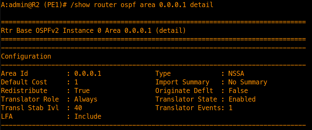
Unlike standard Stub areas where SR OS automatically injects a default summary route, NSSA and Totally NSSA configurations in SR OS leave default route origination disabled (Originate Deflt: False) by default.
To convert Area 1 and 2 to Totally NSSA and ensure downstream routers retain default reachability to the rest of the network, we must combine summaries false (which blocks Type 3 inter-area summaries) with originate-default-route on the ABR:
On Router R2 (PE1) for Area 1
/configure router ospf 0 area 1 nssa summaries false
/configure router ospf 0 area 1 nssa originate-default-route

commit
On Router R5 (PE2) for Area 2
/configure router ospf 0 area 2 nssa summaries false
/configure router ospf 0 area 2 nssa originate-default-route

commit
Implementation Note : If
originate-default-routeis omitted, running/show router ospf area 0.0.0.1 detailon the ABR will showImport Summary: No SummaryalongsideOriginate Deflt: False. This causes the ABR to strip all Type 3 Summary LSAs without injecting a replacing default route, completely isolating the CE router from external and inter-area destinations.
Step 2: Totally NSSA Verification
Once committed, check the link-state database and routing table on your stub-attached edge router (such as R1) to confirm that inter-area summaries have been stripped and replaced by the default route.
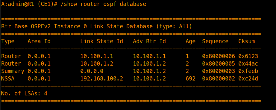
Inspect LSDB on R1 (CE1)
You will see that standard Type 3 network summaries are blocked, and the ABR injects a single default route summary alongside local router LSAs and the Type 7 NSSA entry:
Review Routing Table on R1
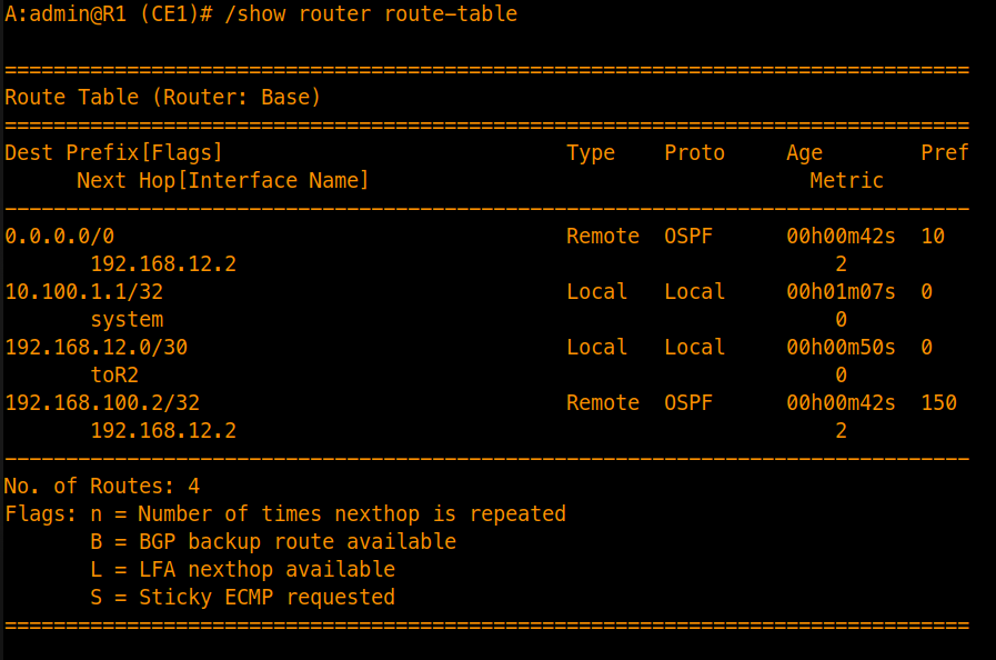
The routing table on the CE router simplifies significantly. Individual inter-area routes are condensed into a single 0.0.0.0/0 default gateway pointing toward the ABR, while the local NSSA-external route remain reachable:
Architectural Note: Overcoming Backbone Disconnection (Virtual Links)
Virtual links are not demonstrated in this lab, but understanding them is important for designing and troubleshooting multi-area topologies where physical connectivity to Area 0 is not always possible.
Backbone Extension & Transit Requirements
OSPF normally requires that all non-backbone areas connect directly back to Area 0 (Backbone). If a physical layout leaves a non-backbone area isolated, a Virtual Link can be used as a workaround.
Functionality: It creates a logical point-to-point tunnel through a normal intermediate transit area to connect the separated area back to the backbone.
Design Constraint: The transit area used for a virtual link cannot be configured as a Stub Area or an NSSA, because those restricted areas drop or modify the transit control traffic needed to maintain the link.
[!NOTE] Virtual links are generally treated as a temporary workaround in production environments. They can complicate IGP troubleshooting at scale and should be avoided in favor of redesigning the area layout where possible.