
In this guide, we establish a 6-node Nokia SR OS baseline in Containerlab and configure the physical interfaces, /30 point-to-point subnets, and system loopbacks required prior to enabling OSPF.
- SR OS Version: 25.7.R1
- CLI Mode: MD-CLI (Model-Driven CLI)
Containerlab Topology File (topology.clab.yml)
name: OSPF-Lab

topology:
  defaults:
    kind: nokia_srsim
    image: localhost/nokia/srsim:25.7.R1
    type: sr-1
    license: license/license.txt

  nodes:
    r1:
      mgmt-ipv4: 172.20.20.9
    r2:
      mgmt-ipv4: 172.20.20.2
    r3:
      mgmt-ipv4: 172.20.20.3
    r4:
      mgmt-ipv4: 172.20.20.4
    r5:
      mgmt-ipv4: 172.20.20.5
    r6:
      mgmt-ipv4: 172.20.20.6

  links:
    # --- CE to PE Links ---
    - endpoints: ["r1:1/1/c1/1", "r2:1/1/c1/1"]
    - endpoints: ["r5:1/1/c1/1", "r6:1/1/c1/1"]

    # --- Core Links ---
    - endpoints: ["r2:1/1/c2/1", "r3:1/1/c1/1"]
    - endpoints: ["r2:1/1/c3/1", "r4:1/1/c1/1"]
    - endpoints: ["r3:1/1/c2/1", "r5:1/1/c2/1"]
    - endpoints: ["r4:1/1/c3/1", "r5:1/1/c3/1"]
Addressing Plan
System (Loopback) Interfaces
| Node | System IP Address | Prefix Length |
|---|---|---|
| R1 | 10.100.1.1 | /32 |
| R2 | 10.100.1.2 | /32 |
| R3 | 10.100.1.3 | /32 |
| R4 | 10.100.1.4 | /32 |
| R5 | 10.100.1.5 | /32 |
| R6 | 10.100.1.6 | /32 |
Physical Interfaces
Router R1
| Interface Name | Port ID | IPv4 Address | Prefix Length | Subnet | Neighbor |
|---|---|---|---|---|---|
| toR2 | 1/1/c1/1 | 192.168.12.1 | 30 | 192.168.12.0/30 | R2 (PE1) |
Router R2
| Interface Name | Port ID | IPv4 Address | Prefix Length | Subnet | Neighbor |
|---|---|---|---|---|---|
| toR1 | 1/1/c1/1 | 192.168.12.2 | 30 | 192.168.12.0/30 | R1 (CE1) |
| toR3 | 1/1/c2/1 | 192.168.23.1 | 30 | 192.168.23.0/30 | R3 (P1) |
| toR4 | 1/1/c3/1 | 192.168.24.1 | 30 | 192.168.24.0/30 | R4 (P2) |
Router R3
| Interface Name | Port ID | IPv4 Address | Prefix Length | Subnet | Neighbor |
|---|---|---|---|---|---|
| toR2 | 1/1/c1/1 | 192.168.23.2 | 30 | 192.168.23.0/30 | R2 (PE1) |
| toR5 | 1/1/c2/1 | 192.168.35.1 | 30 | 192.168.35.0/30 | R5 (PE2) |
Router R4
| Interface Name | Port ID | IPv4 Address | Prefix Length | Subnet | Neighbor |
|---|---|---|---|---|---|
| toR2 | 1/1/c1/1 | 192.168.24.2 | 30 | 192.168.24.0/30 | R2 (PE1) |
| toR5 | 1/1/c3/1 | 192.168.45.1 | 30 | 192.168.45.0/30 | R5 (PE2) |
Router R5
| Interface Name | Port ID | IPv4 Address | Prefix Length | Subnet | Neighbor |
|---|---|---|---|---|---|
| toR3 | 1/1/c2/1 | 192.168.35.2 | 30 | 192.168.35.0/30 | R3 (P1) |
| toR4 | 1/1/c3/1 | 192.168.45.2 | 30 | 192.168.45.0/30 | R4 (P2) |
| toR6 | 1/1/c1/1 | 192.168.56.1 | 30 | 192.168.56.0/30 | R6 (CE2) |
Router R6
| Interface Name | Port ID | IPv4 Address | Prefix Length | Subnet | Neighbor |
|---|---|---|---|---|---|
| toR5 | 1/1/c1/1 | 192.168.56.2 | 30 | 192.168.56.0/30 | R5 (PE2) |
Configuration
Router R1 (CE1)
edit-config global

/configure system name "R1 (CE1)"
/configure card 1 card-type iom-1
/configure card 1 mda 1 mda-type me6-100gb-qsfp28
/configure port 1/1/c1 connector breakout c1-100g
/configure port 1/1/c1 admin-state enable
/configure port 1/1/c1/1 admin-state enable
/configure port 1/1/c1/1 ethernet mode hybrid

/configure router interface "system" admin-state enable
/configure router interface "system" ipv4 primary address 10.100.1.1
/configure router interface "system" ipv4 primary prefix-length 32

/configure router interface "toR2" admin-state enable
/configure router interface "toR2" ipv4 primary address 192.168.12.1
/configure router interface "toR2" ipv4 primary prefix-length 30
/configure router interface "toR2" port 1/1/c1/1:0

commit
Router R2 (PE1)
edit-config global

/configure system name "R2 (PE1)"
/configure card 1 card-type iom-1
/configure card 1 mda 1 mda-type me6-100gb-qsfp28
/configure port 1/1/c1 connector breakout c1-100g
/configure port 1/1/c2 connector breakout c1-100g
/configure port 1/1/c3 connector breakout c1-100g
/configure port 1/1/c1 admin-state enable
/configure port 1/1/c2 admin-state enable
/configure port 1/1/c3 admin-state enable
/configure port 1/1/c1/1 admin-state enable
/configure port 1/1/c1/1 ethernet mode hybrid
/configure port 1/1/c2/1 admin-state enable
/configure port 1/1/c2/1 ethernet mode hybrid
/configure port 1/1/c3/1 admin-state enable
/configure port 1/1/c3/1 ethernet mode hybrid

/configure router interface "system" admin-state enable
/configure router interface "system" ipv4 primary address 10.100.1.2
/configure router interface "system" ipv4 primary prefix-length 32

/configure router interface "toR1" admin-state enable
/configure router interface "toR1" ipv4 primary address 192.168.12.2
/configure router interface "toR1" ipv4 primary prefix-length 30
/configure router interface "toR1" port 1/1/c1/1:0

/configure router interface "toR3" admin-state enable
/configure router interface "toR3" ipv4 primary address 192.168.23.1
/configure router interface "toR3" ipv4 primary prefix-length 30
/configure router interface "toR3" port 1/1/c2/1:0

/configure router interface "toR4" admin-state enable
/configure router interface "toR4" ipv4 primary address 192.168.24.1
/configure router interface "toR4" ipv4 primary prefix-length 30
/configure router interface "toR4" port 1/1/c3/1:0

commit
Router R3 (P1)
edit-config global

/configure system name "R3 (P1)"
/configure card 1 card-type iom-1
/configure card 1 mda 1 mda-type me6-100gb-qsfp28
/configure port 1/1/c1 connector breakout c1-100g
/configure port 1/1/c2 connector breakout c1-100g
/configure port 1/1/c1 admin-state enable
/configure port 1/1/c2 admin-state enable
/configure port 1/1/c1/1 admin-state enable
/configure port 1/1/c1/1 ethernet mode hybrid
/configure port 1/1/c2/1 admin-state enable
/configure port 1/1/c2/1 ethernet mode hybrid

/configure router interface "system" admin-state enable
/configure router interface "system" ipv4 primary address 10.100.1.3
/configure router interface "system" ipv4 primary prefix-length 32

/configure router interface "toR2" admin-state enable
/configure router interface "toR2" ipv4 primary address 192.168.23.2
/configure router interface "toR2" ipv4 primary prefix-length 30
/configure router interface "toR2" port 1/1/c1/1:0

/configure router interface "toR5" admin-state enable
/configure router interface "toR5" ipv4 primary address 192.168.35.1
/configure router interface "toR5" ipv4 primary prefix-length 30
/configure router interface "toR5" port 1/1/c2/1:0

commit
Router R4 (P2)
edit-config global

/configure system name "R4 (P2)"
/configure card 1 card-type iom-1
/configure card 1 mda 1 mda-type me6-100gb-qsfp28
/configure port 1/1/c1 connector breakout c1-100g
/configure port 1/1/c3 connector breakout c1-100g
/configure port 1/1/c1 admin-state enable
/configure port 1/1/c3 admin-state enable
/configure port 1/1/c1/1 admin-state enable
/configure port 1/1/c1/1 ethernet mode hybrid
/configure port 1/1/c3/1 admin-state enable
/configure port 1/1/c3/1 ethernet mode hybrid

/configure router interface "system" admin-state enable
/configure router interface "system" ipv4 primary address 10.100.1.4
/configure router interface "system" ipv4 primary prefix-length 32

/configure router interface "toR2" admin-state enable
/configure router interface "toR2" ipv4 primary address 192.168.24.2
/configure router interface "toR2" ipv4 primary prefix-length 30
/configure router interface "toR2" port 1/1/c1/1:0

/configure router interface "toR5" admin-state enable
/configure router interface "toR5" ipv4 primary address 192.168.45.1
/configure router interface "toR5" ipv4 primary prefix-length 30
/configure router interface "toR5" port 1/1/c3/1:0

commit
Router R5 (PE2)
edit-config global

/configure system name "R5 (PE2)"
/configure card 1 card-type iom-1
/configure card 1 mda 1 mda-type me6-100gb-qsfp28
/configure port 1/1/c1 connector breakout c1-100g
/configure port 1/1/c2 connector breakout c1-100g
/configure port 1/1/c3 connector breakout c1-100g
/configure port 1/1/c1 admin-state enable
/configure port 1/1/c2 admin-state enable
/configure port 1/1/c3 admin-state enable
/configure port 1/1/c1/1 admin-state enable
/configure port 1/1/c1/1 ethernet mode hybrid
/configure port 1/1/c2/1 admin-state enable
/configure port 1/1/c2/1 ethernet mode hybrid
/configure port 1/1/c3/1 admin-state enable
/configure port 1/1/c3/1 ethernet mode hybrid

/configure router interface "system" admin-state enable
/configure router interface "system" ipv4 primary address 10.100.1.5
/configure router interface "system" ipv4 primary prefix-length 32

/configure router interface "toR3" admin-state enable
/configure router interface "toR3" ipv4 primary address 192.168.35.2
/configure router interface "toR3" ipv4 primary prefix-length 30
/configure router interface "toR3" port 1/1/c2/1:0

/configure router interface "toR4" admin-state enable
/configure router interface "toR4" ipv4 primary address 192.168.45.2
/configure router interface "toR4" ipv4 primary prefix-length 30
/configure router interface "toR4" port 1/1/c3/1:0

/configure router interface "toR6" admin-state enable
/configure router interface "toR6" ipv4 primary address 192.168.56.1
/configure router interface "toR6" ipv4 primary prefix-length 30
/configure router interface "toR6" port 1/1/c1/1:0

commit
Router R6 (CE2)
edit-config global

/configure system name "R6 (CE2)"
/configure card 1 card-type iom-1
/configure card 1 mda 1 mda-type me6-100gb-qsfp28
/configure port 1/1/c1 connector breakout c1-100g
/configure port 1/1/c1 admin-state enable
/configure port 1/1/c1/1 admin-state enable
/configure port 1/1/c1/1 ethernet mode hybrid

/configure router interface "system" admin-state enable
/configure router interface "system" ipv4 primary address 10.100.1.6
/configure router interface "system" ipv4 primary prefix-length 32

/configure router interface "toR5" admin-state enable
/configure router interface "toR5" ipv4 primary address 192.168.56.2
/configure router interface "toR5" ipv4 primary prefix-length 30
/configure router interface "toR5" port 1/1/c1/1:0

commit
Verification
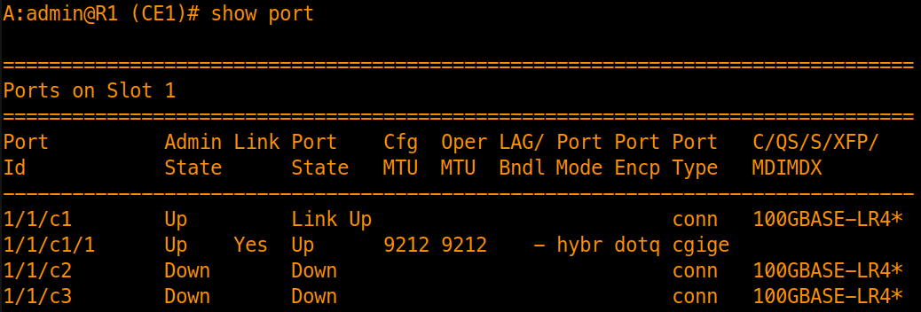
Step 1: Verify Port Operational Status
Verify physical ports are administratively and operationally Up/Up across all routers:
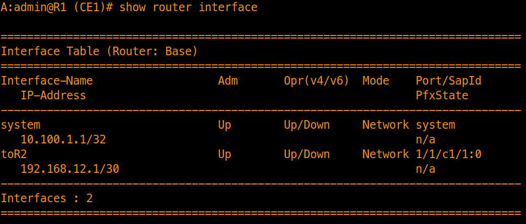
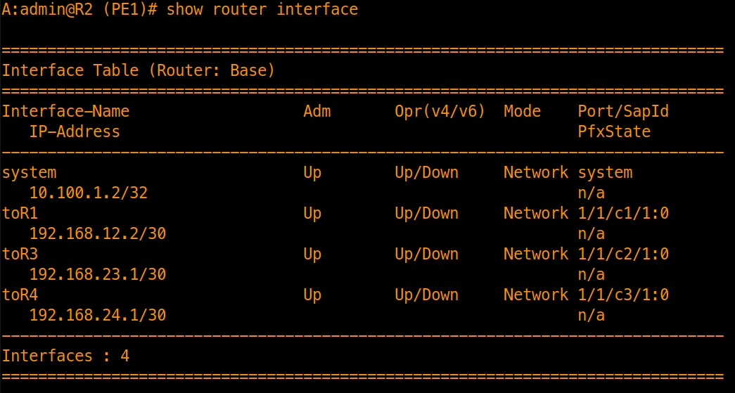
Step 2: Verify Router Interfaces
Confirm system loopbacks and physical interfaces are assigned correct IPs and show operational status Up:
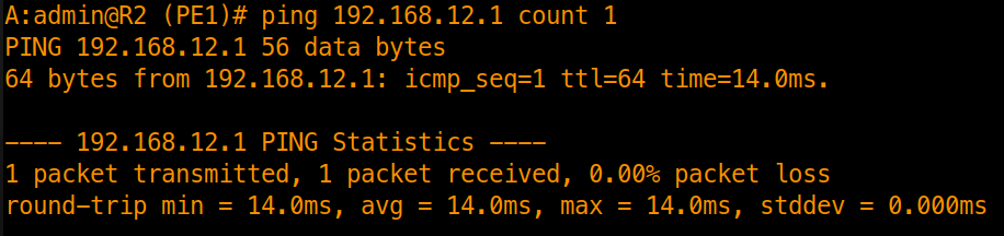
Step 3: Test Direct Physical Link Reachability (Ping)
Verify point-to-point reachability across directly connected links (e.g., pinging R1’s interface 192.168.12.1 from R2):
Step 4: Test Remote Loopback Reachability (Expected Failure)
Confirm that non-adjacent system loopbacks (e.g., R6 from R2) are unreachable prior to routing protocol activation:
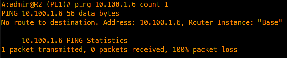
[!NOTE] Without a dynamic routing protocol or static routes, routers only maintain reachability to directly connected subnets. Part 2 covers single-area OSPF configuration to establish full topology reachability.