
This guide covers the design, provisioning, and verification of Multi-Area IS-IS across the Nokia SR OS topology. We examine Level 1 and Level 2 database partitioning, the Attached (ATT) bit default routing mechanism, route summarization with black-hole loop prevention, and policy-based Level 2 to Level 1 route leaking using the Up/Down bit.
- SR OS Version: 25.7.R1
- CLI Mode: MD-CLI (Model-Driven CLI)
[!NOTE] Prerequisites and Physical Foundation: This lab builds directly upon the operational single-area fabric established in IS-IS Part 1: Single-Area Fundamentals, Adjacencies, and LSDB Synchronization. Base interface configuration, card provisioning, port breakouts, and
/30transit links remain in service.
Architecture and NET Addressing
In OSPF, the area boundary resides inside the router: an Area Border Router (ABR) maintains individual interfaces attached to different areas (e.g., Area 0 and Area 1). In IS-IS, the area boundary resides on the link. Every router belongs entirely to a specific area defined by the Area ID component of its Network Entity Title (NET).
To establish an inter-area backbone, routers at the network perimeter run as dual Level 1-2 (L1L2) routers. These routers establish Level 1 adjacencies toward intra-area routers and Level 2 adjacencies across the backbone core.
    [Level 1 (West)]                   [Level 2 Backbone]                   [Level 1 (East)]
  ┌───────────────────────┐   ┌──────────────────────────────────┐   ┌───────────────────────┐
  │                       │   │                                  │   │                       │
  │  +-----------------+  │   │  +-------------+  +-----------+  │   │  +-----------------+  │
  │  |     R1 (CE1)    |  │   │  |   R3 (P1)   |  |  R4 (P2)  |  │   │  |     R6 (CE2)    |  │
  │  |  (L1-Only Node) |  │   │  |  (L2 Core)  |  | (L2 Core) |  │   │  |  (L1-Only Node) |  │
  │  +--------+--------+  │   │  +------+------+  +-----+-----+  │   │  +--------+--------+  │
  │           |           │   │         |               |        │   │           |           │
  │      (L1 Adj)         │   │      (L2 Adj)        (L2 Adj)    │   │      (L1 Adj)         │
  │           |           │   │         |               |        │   │           |           │
  │  +--------+--------+  │   │         |               |        │   │  +--------+--------+  │
  │  |     R2 (PE1)    +--+---+---------+---------------+        │   │  |     R5 (PE2)    |  │
  │  |  (L1/L2 Border) +--+---+---------+---------------+--------+---+--+  (L1/L2 Border) |  │
  │  +-----------------+  │   │                                  │   │  +-----------------+  │
  └───────────────────────┘   └──────────────────────────────────┘   └───────────────────────┘
Addressing Matrix
| Node | Architectural Role | ISO NET Address | Global Capability | Interface Pruning |
|---|---|---|---|---|
| R1 (CE1) | Access CE1 (Area 49.0001) | 49.0001.0101.0000.1001.00 | level-capability 1 | toR2: Level 1 |
| R2 (PE1) | Border PE1 (Area 49.0001) | 49.0001.0101.0000.1002.00 | level-capability 1/2 | toR1: Level 1; toR3, toR4: Level 2 |
| R3 (P1) | Backbone Core P1 (Area 49.0001) | 49.0001.0101.0000.1003.00 | level-capability 2 | toR2, toR5: Level 2 |
| R4 (P2) | Backbone Core P2 (Area 49.0001) | 49.0001.0101.0000.1004.00 | level-capability 2 | toR2, toR5: Level 2 |
| R5 (PE2) | Border PE2 (Area 49.0002) | 49.0002.0101.0000.1005.00 | level-capability 1/2 | toR3, toR4: Level 2; toR6: Level 1 |
| R6 (CE2) | Access CE2 (Area 49.0002) | 49.0002.0101.0000.1006.00 | level-capability 1 | toR5: Level 1 |
[!IMPORTANT] Area ID Assignment on Backbone Routers: Level 2 routers can establish Level 2 adjacencies across different Area IDs or within the same Area ID. In this topology, R3 and R4 reside in Area
49.0001, while R5 and R6 are re-addressed into Area49.0002. Level 2 Hello PDUs omit area match checks, allowing backbone adjacencies to form directly across area boundaries.
Configuration
To reduce control-plane overhead, we prune Hello exchanges at both the instance level (level-capability) and the interface level. By default, Nokia SR OS interfaces send both Level 1 and Level 2 Hellos. Restricting interfaces to the required level eliminates unnecessary Hello traffic.
Router R1 (CE1) - Level 1 Intra-Area Configuration
R1 remains in Area 49.0001 with instance capability set to Level 1:
/configure router isis 0 admin-state enable
/configure router isis 0 area-address 49.0001
/configure router isis 0 level-capability 1
/configure router isis 0 reference-bandwidth 1000 gigabps
/configure router isis 0 authentication-type message-digest
/configure router isis 0 authentication-key "NokiaISIS2026"

/configure router isis 0 interface "system" passive true
/configure router isis 0 interface "system" interface-type point-to-point
/configure router isis 0 interface "system" level-capability 1

/configure router isis 0 interface "toR2" interface-type point-to-point
/configure router isis 0 interface "toR2" level-capability 1
commit
Router R2 (PE1) - Level 1-2 Border Configuration
R2 bridges Area 49.0001 to the Level 2 backbone. Interface toR1 is locked to Level 1, while transit links toR3 and toR4 are locked to Level 2:
/configure router isis 0 admin-state enable
/configure router isis 0 area-address 49.0001
/configure router isis 0 level-capability 1/2
/configure router isis 0 reference-bandwidth 1000 gigabps
/configure router isis 0 authentication-type message-digest
/configure router isis 0 authentication-key "NokiaISIS2026"

/configure router isis 0 interface "system" passive true
/configure router isis 0 interface "system" interface-type point-to-point
/configure router isis 0 interface "system" level-capability 1/2

/configure router isis 0 interface "toR1" interface-type point-to-point
/configure router isis 0 interface "toR1" level-capability 1

/configure router isis 0 interface "toR3" interface-type point-to-point
/configure router isis 0 interface "toR3" level-capability 2

/configure router isis 0 interface "toR4" interface-type point-to-point
/configure router isis 0 interface "toR4" level-capability 2
commit
Routers R3 (P1) and R4 (P2) - Level 2 Backbone
The core transit nodes do not host subscriber endpoints and are restricted globally to Level 2:
# On Router R3 (P1)
/configure router isis 0 admin-state enable
/configure router isis 0 area-address 49.0001
/configure router isis 0 level-capability 2
/configure router isis 0 reference-bandwidth 1000 gigabps
/configure router isis 0 authentication-type message-digest
/configure router isis 0 authentication-key "NokiaISIS2026"

/configure router isis 0 interface "system" passive true
/configure router isis 0 interface "system" interface-type point-to-point
/configure router isis 0 interface "system" level-capability 2

/configure router isis 0 interface "toR2" interface-type point-to-point
/configure router isis 0 interface "toR2" level-capability 2

/configure router isis 0 interface "toR5" interface-type point-to-point
/configure router isis 0 interface "toR5" level-capability 2
commit
# On Router R4 (P2)
/configure router isis 0 admin-state enable
/configure router isis 0 area-address 49.0001
/configure router isis 0 level-capability 2
/configure router isis 0 reference-bandwidth 1000 gigabps
/configure router isis 0 authentication-type message-digest
/configure router isis 0 authentication-key "NokiaISIS2026"

/configure router isis 0 interface "system" passive true
/configure router isis 0 interface "system" interface-type point-to-point
/configure router isis 0 interface "system" level-capability 2

/configure router isis 0 interface "toR2" interface-type point-to-point
/configure router isis 0 interface "toR2" level-capability 2

/configure router isis 0 interface "toR5" interface-type point-to-point
/configure router isis 0 interface "toR5" level-capability 2
commit
Router R5 (PE2) - Level 1-2 Border Configuration (Area 49.0002)
R5 is re-addressed into Area 49.0002. Core-facing links are locked to Level 2, while customer-facing link toR6 is locked to Level 1:
/configure router isis 0 admin-state enable
/configure router isis 0 delete area-address 49.0001
/configure router isis 0 area-address 49.0002
/configure router isis 0 level-capability 1/2
/configure router isis 0 reference-bandwidth 1000 gigabps
/configure router isis 0 authentication-type message-digest
/configure router isis 0 authentication-key "NokiaISIS2026"

/configure router isis 0 interface "system" passive true
/configure router isis 0 interface "system" interface-type point-to-point
/configure router isis 0 interface "system" level-capability 1/2

/configure router isis 0 interface "toR3" interface-type point-to-point
/configure router isis 0 interface "toR3" level-capability 2

/configure router isis 0 interface "toR4" interface-type point-to-point
/configure router isis 0 interface "toR4" level-capability 2

/configure router isis 0 interface "toR6" interface-type point-to-point
/configure router isis 0 interface "toR6" level-capability 1
commit
Router R6 (CE2) - Level 1 Intra-Area Configuration (Area 49.0002)
R6 is re-addressed into Area 49.0002 and restricted to Level 1:
/configure router isis 0 admin-state enable
/configure router isis 0 delete area-address 49.0001
/configure router isis 0 area-address 49.0002
/configure router isis 0 level-capability 1
/configure router isis 0 reference-bandwidth 1000 gigabps
/configure router isis 0 authentication-type message-digest
/configure router isis 0 authentication-key "NokiaISIS2026"

/configure router isis 0 interface "system" passive true
/configure router isis 0 interface "system" interface-type point-to-point
/configure router isis 0 interface "system" level-capability 1

/configure router isis 0 interface "toR5" interface-type point-to-point
/configure router isis 0 interface "toR5" level-capability 1
commit
Adjacency Formation and LSDB Partitioning
Verify adjacencies on border router R2 (PE1):
A:admin@R2 (PE1)# /show router isis 0 adjacency

===============================================================================
Rtr Base ISIS Instance 0 Adjacency
===============================================================================
System ID                Usage State Hold Interface                     MT-ID
-------------------------------------------------------------------------------
R1 (CE1)                 L1    Up    22   toR1                          0
R3 (P1)                  L2    Up    21   toR3                          0
R4 (P2)                  L2    Up    27   toR4                          0
-------------------------------------------------------------------------------
Adjacencies : 3
===============================================================================
R2 maintains:
- A Level 1 adjacency with R1 (CE1) on interface
toR1. - Level 2 adjacencies with core routers R3 (P1) and R4 (P2).
Inspect the Link-State Database on R2 (PE1):
A:admin@R2 (PE1)# /show router isis 0 database

===============================================================================
Rtr Base ISIS Instance 0 Database
===============================================================================
LSP ID                                  Sequence  Checksum Lifetime Attributes
-------------------------------------------------------------------------------

Displaying Level 1 database
-------------------------------------------------------------------------------
R1 (CE1).00-00                          0x5       0x82cb   641      L1
R2 (PE1).00-00                          0x8       0x87b2   642      L1L2 ATT
Level (1) LSP Count : 2

Displaying Level 2 database
-------------------------------------------------------------------------------
R2 (PE1).00-00                          0x8       0x5688   642      L1L2
R3 (P1).00-00                           0x7       0xfa9b   842      L1L2
R4 (P2).00-00                           0x8       0x4f81   769      L1L2
R5 (PE2).00-00                          0x9       0xd2a6   763      L1L2
Level (2) LSP Count : 4
===============================================================================
Key observations from the partitioned database:
- Level 1 Isolation: The Level 1 LSDB on R2 contains only 2 LSPs:
R1 (CE1).00-00andR2 (PE1).00-00. Backbone core and Area49.0002routers are excluded from the Level 1 database. - Backbone Visibility: The Level 2 LSDB contains 4 LSPs representing all Level 2-capable routers in the network (R2, R3, R4, and R5).
- The ATT Bit: In the Level 1 database, R2 advertises
R2 (PE1).00-00with theATT(Attached) attribute set.
The Attached (ATT) Bit and Default Routing
Because Level 1 routers maintain no direct visibility into Level 2 backbone prefixes, IS-IS uses the Attached (ATT) bit to automate egress reachability.
When an L1L2 border router connects to an active Level 2 backbone, it sets the ATT bit (ATT=1) in its Level 1 LSP header. Any Level 1-only router detecting an LSP with ATT=1 automatically calculates and installs a default route (0.0.0.0/0) pointing toward that border router.
Inspect the routing table on R1 (CE1):
A:admin@R1 (CE1)# /show router route-table protocol isis

===============================================================================
Route Table (Router: Base)
===============================================================================
Dest Prefix[Flags]                            Type    Proto     Age        Pref
      Next Hop[Interface Name]                                    Metric
-------------------------------------------------------------------------------
0.0.0.0/0                                     Remote  ISIS      00h13m04s  15
       192.168.12.2                                                 10
10.100.1.2/32                                 Remote  ISIS      00h13m04s  15
       192.168.12.2                                                 10
-------------------------------------------------------------------------------
No. of Routes: 2
Flags: n = Number of times nexthop is repeated
       B = BGP backup route available
       L = LFA nexthop available
       S = Sticky ECMP requested
===============================================================================
R1’s routing table contains 2 routes (down from 10 in Part 1):
10.100.1.2/32: R2’s system loopback.0.0.0.0/0: The dynamically calculated default route pointing to R2 (192.168.12.2).
Verify end-to-end data plane forwarding from R1 to R6 (CE2)’s loopback (10.100.1.6) across the multi-area topology:
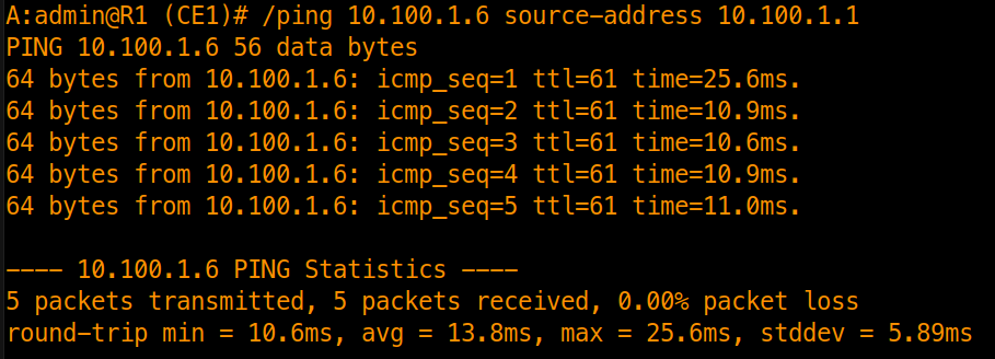
Forwarding succeeds end-to-end despite R1 having no explicit route for 10.100.1.6/32.
Inter-Area Route Summarization
While the default route handles outbound traffic, Level 2 routers learn all individual subnets from attached Level 1 areas. To reduce backbone LSDB scale, L1L2 border routers summarize intra-area subnets into Level 2.
Configure route summarization on R2 (PE1) for the Area 49.0001 address block (10.100.1.0/24):
/configure router isis 0 summary-address 10.100.1.0/24 level-capability 2
commit
Black Hole Loop Prevention Route
When summarization is configured, SR OS installs a Black Hole route for the aggregate prefix into R2’s FIB:
A:admin@R2 (PE1)# /show router route-table 10.100.1.0/24

===============================================================================
Route Table (Router: Base)
===============================================================================
Dest Prefix[Flags]                            Type    Proto     Age        Pref
      Next Hop[Interface Name]                                    Metric
-------------------------------------------------------------------------------
10.100.1.0/24                                 Blackh* ISIS      00h01m09s  255
       Black Hole                                                   1
-------------------------------------------------------------------------------
No. of Routes: 1
Flags: n = Number of times nexthop is repeated
       B = BGP backup route available
       L = LFA nexthop available
       S = Sticky ECMP requested
===============================================================================
* indicates that the corresponding row element may have been truncated.
[!NOTE] Loop Prevention Mechanics: If traffic arrives at R2 addressed to an unassigned IP within
10.100.1.0/24, the longest-prefix match forwards it to theBlackh*route, silently dropping it. This prevents packets from looping between R2 and core routers that forward toward R2 based on the summary route.
Inspect the Level 2 LSP of R2 on core router R3 (P1) to verify that only the aggregate prefix is flooded into the backbone:
A:admin@R3 (P1)# /show router isis 0 database "R2 (PE1).00-00" level 2 detail | match 10.100.1.
    Router ID   : 10.100.1.2
    IP Address    : 10.100.1.0
    I/F Address   : 10.100.1.2
    Prefix   : 10.100.1.0
Policy-Based Level 2 to Level 1 Route Leaking
Relying exclusively on the ATT bit can cause sub-optimal routing.
Because Level 1 routers only maintain a default route pointing to the nearest L1L2 border router, they have no visibility into cumulative path costs across the backbone. In topologies with multiple L1L2 exit points, an L1 router forwards to the nearest border router, even if another exit router offers a lower overall metric to the destination.
IS-IS addresses this with Route Leaking: injecting specific Level 2 prefixes into Level 1.
Configuring the Leaking Policy on Border Router R2 (PE1)
Create a prefix-list matching R6 (CE2)’s system loopback and leak it from Level 2 into Level 1:
/configure policy-options prefix-list "r6-loopback" prefix 10.100.1.6/32 type exact

/configure policy-options policy-statement "leak-l2-to-l1" entry 10 from level 2
/configure policy-options policy-statement "leak-l2-to-l1" entry 10 from prefix-list ["r6-loopback"]
/configure policy-options policy-statement "leak-l2-to-l1" entry 10 to level 1
/configure policy-options policy-statement "leak-l2-to-l1" entry 10 action action-type accept

/configure router isis 0 export-policy ["leak-l2-to-l1"]
commit
The Up/Down Bit (Loop Prevention)
When an L1L2 router leaks a prefix from Level 2 down into Level 1, it sets the Down bit (Up/Down bit) to 1 within the IP reachability TLV (TLV 135).
The Down bit enforces a strict loop-prevention rule:
- A prefix with
Down=0originated inside Level 1 and can be advertised up into Level 2. - A prefix with
Down=1originated in Level 2 and was leaked into Level 1. L1L2 routers never re-advertise a prefix withDown=1back into Level 2.
Inspect R2’s Level 1 LSP detail on R1 (CE1) to confirm the leaked prefix:
A:admin@R1 (CE1)# /show router isis 0 database "R2 (PE1).00-00" level 1 detail | match 10.100.1.6 post-lines 5
    IP Address    : 10.100.1.6
    IP Mask       : 255.255.255.255
  I/F Addresses :
    I/F Address   : 10.100.1.2
    I/F Address   : 192.168.12.2
  TE IS Nbrs   :
    Prefix   : 10.100.1.6
  Authentication:
    Auth Type     : MD5(54) (16 bytes)
    Auth Info     : 6615a9cce8e83d94a8fe329799958f6b
Level (1) LSP Count : 1
-------------------------------------------------------------------------------
Inspect R1 (CE1)’s routing table:
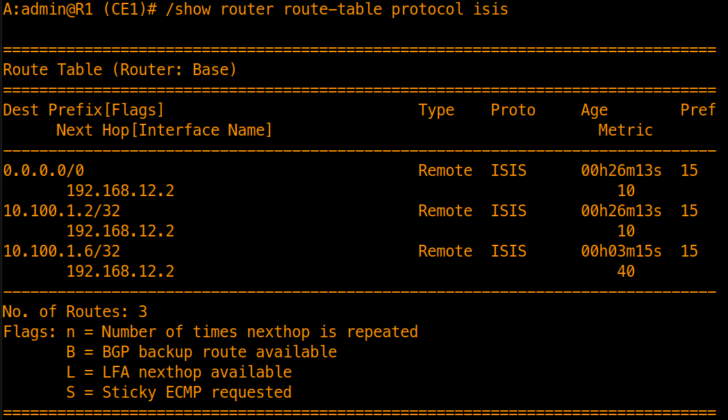
R1 installs the specific route for 10.100.1.6/32 with metric 40 alongside the fallback default route.