This guide covers Single-Area IS-IS (Area 49.0001) configuration across a 6-node Nokia SR OS topology in Containerlab, ISO Network Entity Title (NET) addressing, point-to-point adjacency formation, and Link-State Database (LSDB) synchronization.
- SR OS Version: 25.7.R1
- CLI Mode: MD-CLI (Model-Driven CLI)
[!NOTE] Base Interface Prerequisites: This lab builds upon the physical foundation established in OSPF Part 1: Topology Setup and Interface Addressing. Ensure that cards (
iom-1), MDAs (me6-100gb-qsfp28), port breakouts (port 1/1/c1 connector breakout c1-100g), system loopbacks, and/30point-to-point IP interfaces are operational prior to activating IS-IS.
Architecture and NET Addressing
Unlike OSPF where routing processes and interfaces are identified by 32-bit IPv4 Router IDs, IS-IS runs directly on the Data Link Layer (Layer 2) using ISO/OSI encapsulation. In IS-IS, the router itself is addressed using a Network Entity Title (NET).
A NET address is a specialized variation of an ISO NSAP (Network Service Access Point) address. It ranges from 8 to 20 bytes long (typically configured as 10 bytes) and is formatted as a series of hexadecimal characters separated by dots. In a NET, the trailing N-Selector (N-SEL) byte is always set to 00, designating the network layer process of the router itself rather than an upper-layer transport service.
NET Address Format
A Network Entity Title comprises three structured components:
Area ID (1-13 Bytes)      System ID (6 Bytes)       N-SEL (1 Byte)
+-----------------------+-------------------------+----------------+
|        49.0001        |   0101 . 0000 . 1001    |       00       |
+-----------------------+-------------------------+----------------+
- Area ID (
49.0001): Variable length from 1 to 13 bytes (typically 3 bytes in IP networks). AFI49defines an ISO locally assigned private address space, followed by Area0001. - System ID (
0101.0000.1001): A fixed 6-byte identifier uniquely identifying the router within the area. In IP networks, this is derived from the system loopback IP:- IP
10.100.1.1→ pad each octet to 3 digits:010.100.001.001→ group into 4-character blocks:0101.0000.1001.
- IP
- N-Selector (
00): Identifies the network service entity (always00for a router node, completing the 10-byte total NET length: 3 bytes Area + 6 bytes System ID + 1 byte N-SEL).
In Nokia SR OS MD-CLI, the area address is configured under /configure router isis 0 area-address 49.0001. SR OS pairs the configured area with the router’s system interface IP to form the complete NET.
ISO NET Addressing Plan
R1 (CE1) --- R2 (PE1) === R3 (P1) / R4 (P2) === R5 (PE2) --- R6 (CE2)
The table below outlines the IS-IS ISO NET addressing plan derived from each node’s loopback interface:
| Node | Role | System IPv4 | System ID | ISO NET Address |
|---|---|---|---|---|
| R1 | CE1 | 10.100.1.1/32 | 0101.0000.1001 | 49.0001.0101.0000.1001.00 |
| R2 | PE1 | 10.100.1.2/32 | 0101.0000.1002 | 49.0001.0101.0000.1002.00 |
| R3 | P1 | 10.100.1.3/32 | 0101.0000.1003 | 49.0001.0101.0000.1003.00 |
| R4 | P2 | 10.100.1.4/32 | 0101.0000.1004 | 49.0001.0101.0000.1004.00 |
| R5 | PE2 | 10.100.1.5/32 | 0101.0000.1005 | 49.0001.0101.0000.1005.00 |
| R6 | CE2 | 10.100.1.6/32 | 0101.0000.1006 | 49.0001.0101.0000.1006.00 |
Configuration
Enable IS-IS instance 0, set the area address to 49.0001, limit adjacencies to Level 1 (level-capability 1), set reference-bandwidth to 1000 gigabps, configure physical interfaces as point-to-point, and secure links with MD5 authentication.
Router R1 (CE1)
/configure router isis 0 admin-state enable
/configure router isis 0 area-address 49.0001
/configure router isis 0 level-capability 1
/configure router isis 0 reference-bandwidth 1000 gigabps
/configure router isis 0 authentication-type message-digest
/configure router isis 0 authentication-key "NokiaISIS2026"
/configure router isis 0 interface "system" passive true
/configure router isis 0 interface "system" interface-type point-to-point
/configure router isis 0 interface "toR2" interface-type point-to-point

commit
Router R2 (PE1)
/configure router isis 0 admin-state enable
/configure router isis 0 area-address 49.0001
/configure router isis 0 level-capability 1
/configure router isis 0 reference-bandwidth 1000 gigabps
/configure router isis 0 authentication-type message-digest
/configure router isis 0 authentication-key "NokiaISIS2026"
/configure router isis 0 interface "system" passive true
/configure router isis 0 interface "system" interface-type point-to-point
/configure router isis 0 interface "toR1" interface-type point-to-point
/configure router isis 0 interface "toR3" interface-type point-to-point
/configure router isis 0 interface "toR4" interface-type point-to-point

commit
Router R3 (P1)
/configure router isis 0 admin-state enable
/configure router isis 0 area-address 49.0001
/configure router isis 0 level-capability 1
/configure router isis 0 reference-bandwidth 1000 gigabps
/configure router isis 0 authentication-type message-digest
/configure router isis 0 authentication-key "NokiaISIS2026"
/configure router isis 0 interface "system" passive true
/configure router isis 0 interface "system" interface-type point-to-point
/configure router isis 0 interface "toR2" interface-type point-to-point
/configure router isis 0 interface "toR5" interface-type point-to-point

commit
Router R4 (P2)
/configure router isis 0 admin-state enable
/configure router isis 0 area-address 49.0001
/configure router isis 0 level-capability 1
/configure router isis 0 reference-bandwidth 1000 gigabps
/configure router isis 0 authentication-type message-digest
/configure router isis 0 authentication-key "NokiaISIS2026"
/configure router isis 0 interface "system" passive true
/configure router isis 0 interface "system" interface-type point-to-point
/configure router isis 0 interface "toR2" interface-type point-to-point
/configure router isis 0 interface "toR5" interface-type point-to-point

commit
Router R5 (PE2)
/configure router isis 0 admin-state enable
/configure router isis 0 area-address 49.0001
/configure router isis 0 level-capability 1
/configure router isis 0 reference-bandwidth 1000 gigabps
/configure router isis 0 authentication-type message-digest
/configure router isis 0 authentication-key "NokiaISIS2026"
/configure router isis 0 interface "system" passive true
/configure router isis 0 interface "system" interface-type point-to-point
/configure router isis 0 interface "toR3" interface-type point-to-point
/configure router isis 0 interface "toR4" interface-type point-to-point
/configure router isis 0 interface "toR6" interface-type point-to-point

commit
Router R6 (CE2)
/configure router isis 0 admin-state enable
/configure router isis 0 area-address 49.0001
/configure router isis 0 level-capability 1
/configure router isis 0 reference-bandwidth 1000 gigabps
/configure router isis 0 authentication-type message-digest
/configure router isis 0 authentication-key "NokiaISIS2026"
/configure router isis 0 interface "system" passive true
/configure router isis 0 interface "system" interface-type point-to-point
/configure router isis 0 interface "toR5" interface-type point-to-point

commit
Verification
1. Verifying IS-IS Interfaces
Verify that all interfaces show operational state Up and network type p2p:
A:admin@R2 (PE1)# /show router isis 0 interface

===============================================================================
Rtr Base ISIS Instance 0 Interfaces
===============================================================================
Interface                        Level CircID  Oper      L1/L2 Metric     Type
                                               State
-------------------------------------------------------------------------------
system                           L1L2  1       Up        0/0              p2p
toR1                             L1L2  2       Up        10/10            p2p
toR3                             L1L2  3       Up        10/10            p2p
toR4                             L1L2  4       Up        10/10            p2p
-------------------------------------------------------------------------------
Interfaces : 4
===============================================================================
2. Checking Adjacency States
Verify that neighboring routers have formed bidirectional Level 1 adjacencies:
A:admin@R2 (PE1)# /show router isis 0 adjacency

===============================================================================
Rtr Base ISIS Instance 0 Adjacency
===============================================================================
System ID                Usage State Hold Interface                     MT-ID
-------------------------------------------------------------------------------
R1 (CE1)                 L1    Up    19   toR1                          0
R3 (P1)                  L1    Up    24   toR3                          0
R4 (P2)                  L1    Up    24   toR4                          0
-------------------------------------------------------------------------------
Adjacencies : 3
===============================================================================
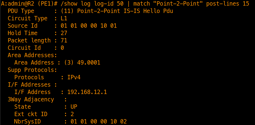
3. Point-to-Point Three-Way Adjacency (RFC 5303)
Standard ISO 10589 uses a 2-way handshake on point-to-point links, which cannot detect unidirectional link failures. RFC 5303 defines the Point-to-Point Three-Way Adjacency Option (TLV 240), transitioning through DOWN → INIT → UP.
We configure a dedicated memory log (log-id 50) to trace IS-IS packet exchanges:
edit-config global

/configure log log-id 50 description "IS-IS Packet Trace"
/configure log log-id 50 source debug
/configure log log-id 50 destination memory max-entries 200

commit

//debug router isis packet detail
Inspecting the debug log displays the received Point-to-Point Hello PDU carrying the RFC 5303 Three-Way Adjacency TLV:
4. Link-State Database (LSDB) Inspection
Verify that all routers hold consistent copies of the Level 1 LSDB:
A:admin@R1 (CE1)# /show router isis 0 database

===============================================================================
Rtr Base ISIS Instance 0 Database
===============================================================================
LSP ID                                  Sequence  Checksum Lifetime Attributes
-------------------------------------------------------------------------------

Displaying Level 1 database
-------------------------------------------------------------------------------
R1 (CE1).00-00                          0x3       0x33f    1153     L1
R2 (PE1).00-00                          0x5       0xc80f   1155     L1
R3 (P1).00-00                           0x4       0xd2fb   1155     L1
R4 (P2).00-00                           0x3       0x764f   1152     L1
R5 (PE2).00-00                          0x6       0xf14c   1154     L1
R6 (CE2).00-00                          0x5       0xe180   1149     L1
Level (1) LSP Count : 6

Displaying Level 2 database
-------------------------------------------------------------------------------
Level (2) LSP Count : 0
===============================================================================
LSP ID Breakdown: R1 (CE1).00-00
R1 (CE1): System name associated with System ID0101.0000.1001..00: Pseudonode Identifier. Zero (00) indicates a real router LSP. Non-zero values indicate a broadcast LAN pseudonode.-00: LSP Fragment Number. Used when an LSP exceeds MTU.
Inspecting the detailed LSP output displays TLVs carried inside:
A:admin@R1 (CE1)# /show router isis 0 database "R1 (CE1).00-00" detail

===============================================================================
Rtr Base ISIS Instance 0 Database (detail)
===============================================================================

Displaying Level 1 database
-------------------------------------------------------------------------------
LSP ID    : R1 (CE1).00-00                              Level     : L1
Sequence  : 0x4                    Checksum  : 0xb070   Lifetime  : 1080
Version   : 1                      Pkt Type  : 18       Pkt Ver   : 1
Attributes: L1                     Max Area  : 3        Alloc Len : 1492
SYS ID    : 0101.0000.1001         SysID Len : 6        Used Len  : 166

TLVs :
  Area Addresses:
    Area Address : (3) 49.0001
  Supp Protocols:
    Protocols     : IPv4
  IS-Hostname   : R1 (CE1)
  Router ID   :
    Router ID   : 10.100.1.1
  IS Neighbors  :
    Virtual Flag  : 0
    Default Metric: (I) 10
    Delay Metric  : (I) 0
    Expense Metric: (I) 0
    Error Metric  : (I) 0
    Neighbor      : R2 (PE1).00
  Internal Reach:
    Default Metric: (I) 10
    Delay Metric  : (I) 0
    Expense Metric: (I) 0
    Error Metric  : (I) 0
    IP Address    : 192.168.12.0
    IP Mask       : 255.255.255.252
    Default Metric: (I) 0
    Delay Metric  : (I) 0
    Expense Metric: (I) 0
    Error Metric  : (I) 0
    IP Address    : 10.100.1.1
    IP Mask       : 255.255.255.255
  I/F Addresses :
    I/F Address   : 10.100.1.1
    I/F Address   : 192.168.12.1
  TE IS Nbrs   :
    Nbr   : R2 (PE1).00
    Default Metric  : 10
    Sub TLV Len     : 12
    IF Addr   : 192.168.12.1
    Nbr IP    : 192.168.12.2
  TE IP Reach   :
    Default Metric  : 10
    Control Info:    , prefLen 30
    Prefix   : 192.168.12.0
    Default Metric  : 0
    Control Info:    , prefLen 32
    Prefix   : 10.100.1.1
  Authentication:
    Auth Type     : MD5(54) (16 bytes)
    Auth Info     : ed3c5bf81674ca6f87c2420b7ad66b34

Level (1) LSP Count : 1

Displaying Level 2 database
-------------------------------------------------------------------------------
Level (2) LSP Count : 0
===============================================================================
5. Point-to-Point vs. Broadcast (DIS Mechanics)
On broadcast interfaces, IS-IS elects a Designated Intermediate System (DIS) to represent the multi-access segment as a pseudonode.
To observe this, change the interface type on both ends of the link between R1 (CE1) and R2 (PE1) to broadcast (IS-IS requires matching interface types on both endpoints to establish an adjacency):
# On Router R1 (CE1)
/configure router isis 0 interface "toR2" interface-type broadcast
commit

# On Router R2 (PE1)
/configure router isis 0 interface "toR1" interface-type broadcast
commit
Inspecting the interface detail on R1 (CE1) and R2 (PE1) reveals the elected DIS:
A:admin@R1 (CE1)# /show router isis 0 interface "toR2" detail | match "Desg. IS"
  Desg. IS      : R1 (CE1)
  Desg. IS      : R1 (CE1)

A:admin@R2 (PE1)# /show router isis 0 interface "toR1" detail | match "Desg. IS"
  Desg. IS      : R1 (CE1)
  Desg. IS      : R2 (PE1)
The command yields two entries per interface because level-capability defaults to L1L2. In Level 1, both routers agree that R1 (CE1) is the DIS. With both routers configured with the default DIS priority of 64, the tie-breaker is decided by the highest Subnetwork Point of Attachment (SNPA/MAC address) on the link. In Level 2, no adjacency exists (Adjacencies : 0), causing each router to locally designate itself.
Once elected on a broadcast segment, the DIS generates a Pseudonode LSP representing the multi-access LAN. Verifying the Level 1 LSDB on R1 (CE1) confirms the database count increased from 6 to 7:
A:admin@R1 (CE1)# /show router isis 0 database

===============================================================================
Rtr Base ISIS Instance 0 Database
===============================================================================
LSP ID                                  Sequence  Checksum Lifetime Attributes
-------------------------------------------------------------------------------

Displaying Level 1 database
-------------------------------------------------------------------------------
R1 (CE1).00-00                          0x7       0x1539   953      L1
R1 (CE1).02-00                          0x1       0x2bda   953      L1
R2 (PE1).00-00                          0xf       0xde52   952      L1
R3 (P1).00-00                           0xa       0x56bb   867      L1
R4 (P2).00-00                           0x8       0xb63e   871      L1
R5 (PE2).00-00                          0xc       0x560    866      L1
R6 (CE2).00-00                          0x9       0x806f   855      L1
Level (1) LSP Count : 7

Displaying Level 2 database
-------------------------------------------------------------------------------
Level (2) LSP Count : 0
===============================================================================
The new LSP R1 (CE1).02-00 is the Pseudonode LSP:
R1 (CE1): The DIS router that originated the pseudonode..02: The local Circuit ID of interfacetoR2on R1 (CE1).-00: The LSP fragment number.
Differences between IS-IS DIS and OSPF DR:
| Attribute | IS-IS DIS | OSPF DR |
|---|---|---|
| Backup Router | None (no BDR) | BDR elected |
| Preemption | Preemptive | Non-preemptive |
| Default Priority | 64 (0–127) | 1 (0–255) |
| Pseudonode LSP | R1 (CE1).02-00 | Network LSA (Type 2) |
6. End-to-End Route Validation
Verify the route table on R1 (CE1) for all remote loopback and transit subnets:
A:admin@R1 (CE1)# /show router route-table protocol isis

===============================================================================
Route Table (Router: Base)
===============================================================================
Dest Prefix[Flags]                            Type    Proto     Age        Pref
      Next Hop[Interface Name]                                    Metric
-------------------------------------------------------------------------------
10.100.1.2/32                                 Remote  ISIS      00h00m54s  15
       192.168.12.2                                                 10
10.100.1.3/32                                 Remote  ISIS      00h00m54s  15
       192.168.12.2                                                 20
10.100.1.4/32                                 Remote  ISIS      00h00m54s  15
       192.168.12.2                                                 20
10.100.1.5/32                                 Remote  ISIS      00h00m27s  15
       192.168.12.2                                                 30
10.100.1.6/32                                 Remote  ISIS      00h00m22s  15
       192.168.12.2                                                 40
192.168.23.0/30                               Remote  ISIS      00h00m54s  15
       192.168.12.2                                                 20
192.168.24.0/30                               Remote  ISIS      00h00m54s  15
       192.168.12.2                                                 20
192.168.35.0/30                               Remote  ISIS      00h00m54s  15
       192.168.12.2                                                 30
192.168.45.0/30                               Remote  ISIS      00h00m54s  15
       192.168.12.2                                                 30
192.168.56.0/30                               Remote  ISIS      00h00m27s  15
       192.168.12.2                                                 40
-------------------------------------------------------------------------------
No. of Routes: 10
===============================================================================
7. End-to-End Data Plane Verification
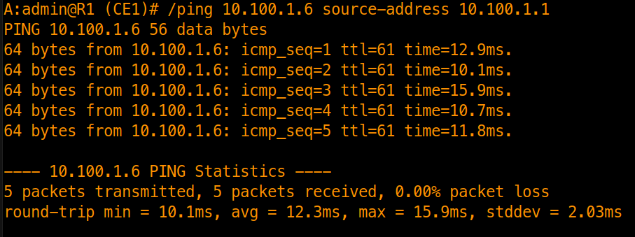
Execute an end-to-end ping from R1 (CE1) across the network topology to R6 (CE2)’s system loopback (10.100.1.6):