Segmenting corporate networks into logical VLANs isolates broadcast domains, but without explicit access controls, inter-VLAN routing allows unrestricted traffic flow between subnets.
To enforce security parameters at the network perimeter, engineers use Access Control Lists (ACLs) to filter traffic between guest networks and critical internal assets.
Lab Objective: Build a Router-on-a-Stick (ROAS) architecture using 802.1Q trunks, configure router-based DHCP services, and apply an Extended ACL to block guest VLAN traffic from accessing the internal server.
📁 Lab File: Download the Inter-VLAN Routing and Guest Isolation Packet Tracer Lab (.pkt).
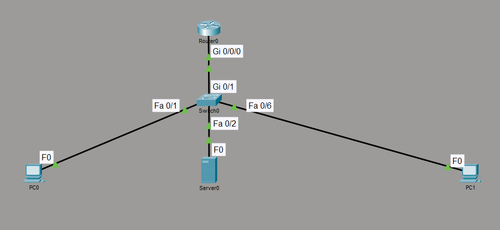
Topology
In this lab, we use a Cisco 4331 ISR, a Catalyst 2960 switch, and three end devices.
| Source Device | Interface | Destination Device | Interface | Assigned VLAN |
|---|---|---|---|---|
| Switch0 | Gi0/1 | Router0 | Gi0/0/0 | Trunk (802.1Q) |
| Switch0 | Fa0/1 | PC0 (Employee) | Fa0 | VLAN 10 |
| Switch0 | Fa0/2 | Server0 (Internal) | Fa0 | VLAN 10 |
| Switch0 | Fa0/6 | PC1 (Guest) | Fa0 | VLAN 20 |
Switch Configuration (VLANs & Trunks)
Provision VLAN 10 (Employee) and VLAN 20 (Guest), assign access interfaces, and configure the trunk uplink to the router.
! --- Create VLANs ---
enable
configure terminal
hostname Switch0

vlan 10
 name Employee

vlan 20
 name Guest
exit

! --- Assign Employee Access Ports ---
interface range fa0/1 - 5
 switchport mode access
 switchport access vlan 10
exit

! --- Assign Guest Access Ports ---
interface range fa0/6 - 10
 switchport mode access
 switchport access vlan 20
exit

! --- Configure 802.1Q Trunk to Router ---
interface gig0/1
 switchport mode trunk
exit
Router Configuration (ROAS & DHCP Pools)
Enable the physical interface, define 802.1Q sub-interfaces for inter-VLAN routing, and configure pool exclusions and DHCP pools.
! --- System & Physical Interface Setup ---
enable
configure terminal
hostname Router0

interface gig0/0/0
 no shutdown
exit

! --- Sub-interface: VLAN 10 (Employee Gateway) ---
interface gig0/0/0.10
 encapsulation dot1Q 10
 ip address 192.168.10.1 255.255.255.0
exit

! --- Sub-interface: VLAN 20 (Guest Gateway) ---
interface gig0/0/0.20
 encapsulation dot1Q 20
 ip address 192.168.20.1 255.255.255.0
exit

! --- Exclude Static Infrastructure IPs ---
ip dhcp excluded-address 192.168.10.1
ip dhcp excluded-address 192.168.10.50
ip dhcp excluded-address 192.168.20.1

! --- DHCP Pool: Employee Network ---
ip dhcp pool EMPLOYEE_POOL
 network 192.168.10.0 255.255.255.0
 default-router 192.168.10.1
 dns-server 8.8.8.8
exit

! --- DHCP Pool: Guest Network ---
ip dhcp pool GUEST_POOL
 network 192.168.20.0 255.255.255.0
 default-router 192.168.20.1
 dns-server 8.8.8.8
exit
Access Control List Configuration (Router)
To prevent guests from traversing inter-VLAN routing into the 192.168.10.0/24 subnet, apply an Extended Named ACL inbound on the guest sub-interface (Gi0/0/0.20).
Extended ACLs filter as close to the source as possible based on source and destination parameters.
! --- Define Extended ACL ---
ip access-list extended BLOCK_GUEST
 deny ip 192.168.20.0 0.0.0.255 192.168.10.0 0.0.0.255
 permit ip any any
exit

! --- Apply ACL to Guest Gateway Sub-interface ---
interface gig0/0/0.20
 ip access-group BLOCK_GUEST in
exit
End-Device Addressing (Desktop > IP Configuration)
Configure static parameters on Server0. PC0 and PC1 obtain their IP parameters dynamically via the router’s DHCP pools.
| Device | IP Address Assignment | Subnet Mask | Default Gateway |
|---|---|---|---|
| PC0 (Employee) | Dynamic (DHCP: 192.168.10.2) | 255.255.255.0 | 192.168.10.1 |
| Server0 (Internal) | Static: 192.168.10.50 | 255.255.255.0 | 192.168.10.1 |
| PC1 (Guest) | Dynamic (DHCP: 192.168.20.2) | 255.255.255.0 | 192.168.20.1 |
Verification
Validate inter-VLAN routing and ACL enforcement from the end-device command prompts (Desktop > Command Prompt).
Verify Internal VLAN Access (Employee to Server):
From
PC0, ping the internal server address:ping 192.168.10.50Result: Replies are received successfully across VLAN 10.
Verify Guest Network Isolation (ACL Enforcement):
From
PC1, attempt to ping the internal server across the router:ping 192.168.10.50Result: Output displays
Destination host unreachable. as the inbound ACL onGi0/0/0.20drops the traffic.Verify Local Gateway Reachability:
From
PC1, ping its default gateway:ping 192.168.20.1Result: Replies are received, confirming local connectivity and external internet reachability (
via permit ip any any).Inspect ACL Matches on Router:
Execute
show ip access-listsonRouter0to verify match counters for dropped packets:Router0# show ip access-lists BLOCK_GUEST Extended IP access list BLOCK_GUEST deny ip 192.168.20.0 0.0.0.255 192.168.10.0 0.0.0.255 (4 match (es)) permit ip any any (6 match (es))