A single default gateway represents a critical single point of failure in enterprise access layer networks. If a primary router loses power, suffers a link failure, or reboots, end hosts remain isolated from external subnets, even if a physical backup router is online and connected to the same switch.
First Hop Redundancy Protocols (FHRP) solve this by allowing multiple physical routers to share a single Virtual IP (VIP) and Virtual MAC address. Hosts target the Virtual IP as their default gateway, ensuring transparent, automatic failover without requiring IP reconfiguration or ARP table flushes on client devices.
Lab Objective: Implement Cisco Hot Standby Router Protocol (HSRP) across two routers sharing a common LAN segment, tune priority and preemption settings to control active gateway election, and verify data plane continuity during a simulated router crash.
📁 Lab File: Download the HSRP High Availability Gateway Packet Tracer Lab (.pkt).
Topology
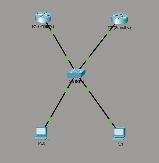
The topology features two Cisco ISR routers (R1 and R2) connected via an access switch (Switch0) to a shared LAN segment (192.168.1.0/24). R1 serves as the primary gateway, R2 acts as the standby failover node, and hosts (PC0, PC1) send default traffic to the HSRP Virtual IP 192.168.1.1.
| Device | Interface | Physical IP Address | Subnet Mask | HSRP Role | HSRP Priority | Virtual IP (VIP) |
|---|---|---|---|---|---|---|
| R1 | Gi0/0/0 | 192.168.1.2 | 255.255.255.0 | Active Gateway | 110 | 192.168.1.1 |
| R2 | Gi0/0/0 | 192.168.1.3 | 255.255.255.0 | Standby Gateway | 100 (Default) | 192.168.1.1 |
| PC0 | Fa0 | 192.168.1.10 | 255.255.255.0 | Host Client | N/A | Default GW: 192.168.1.1 |
| PC1 | Fa0 | 192.168.1.11 | 255.255.255.0 | Host Client | N/A | Default GW: 192.168.1.1 |
Router Configuration
Configure interface addressing, initialize HSRP Group 1, adjust priority levels to elect R1 as the active router, and enable preemption on the primary node.
R1 Router (Primary Active Gateway)
enable
configure terminal
hostname R1

! --- LAN Gateway Interface ---
interface GigabitEthernet0/0/0
 description Primary Gateway Interface to LAN
 ip address 192.168.1.2 255.255.255.0

 ! --- HSRP Group 1 Configuration ---
 standby 1 ip 192.168.1.1
 standby 1 priority 110
 standby 1 preempt
 no shutdown
exit
R2 Router (Secondary Standby Gateway)
enable
configure terminal
hostname R2

! --- Configure Physical Gateway Interface ---
interface GigabitEthernet0/0/0
 description Backup Gateway Interface
 ip address 192.168.1.3 255.255.255.0

 ! --- HSRP Group 1 Configuration ---
 standby 1 ip 192.168.1.1
 standby 1 priority 100
 no shutdown
exit
Verification
Validate active/standby status elections, inspect virtual MAC assignments, and test traffic failover during a simulated primary node failure.
Confirm HSRP Role Assignment:
Execute
show standby briefon R1 and R2 to confirm state convergence:R1# show standby brief P indicates configured to preempt. | Interface Grp Pri P State Active Standby Virtual IP Gig0/0/0 1 110 P Active local 192.168.1.3 192.168.1.1R2# show standby brief P indicates configured to preempt. | Interface Grp Pri P State Active Standby Virtual IP Gig0/0/0 1 100 Standby 192.168.1.2 local 192.168.1.1Result:
R1assumes theActiverole due to its higher priority (110 vs. 100), whileR2remains inStandby.Inspect Host ARP Table:
Ping the Virtual IP (
192.168.1.1) fromPC0and check its ARP cache (arp -a):C:\> arp -a Internet Address Physical Address Type 192.168.1.1 0000.0c07.ac01 dynamicResult: The ARP table resolves the Virtual IP (
192.168.1.1) to the HSRP Virtual MAC address0000.0c07.ac01(0000.0c= Cisco OUI,07.ac= HSRP IPv4 identifier,01= Group 1).Simulate Primary Gateway Failover:
From PC0, initiate a continuous ping to the gateway, then shut down R1’s active interface:
C:\> ping -t 192.168.1.1On R1:
R1(config)# interface GigabitEthernet0/0/0
R1(config-if)# shutdown
Verify Failover Convergence:
Check the HSRP role status on
R2followingR1’s interface shutdown:R2# show standby brief P indicates configured to preempt. | Interface Grp Pri P State Active Standby Virtual IP Gig0/0/0 1 100 Active local unknown 192.168.1.1Result:
R2detects missing HSRP hello packets from R1, transitions fromStandbytoActive, and resumes forwarding traffic for192.168.1.1with minimal packet loss.Verify Preemption
Re-enable the interface on R1:
R1(config)# interface GigabitEthernet0/0/0
R1(config-if)# no shutdown
Result: Because
standby 1 preemptwas configured on R1, R1 reclaims theActiverole from R2 upon recovery.
Takeaways
The Virtual MAC Mechanism: HSRP hosts send frames targeted to the Virtual MAC address (
0000.0c07.acXX). When failover occurs, R2 sends a gratuitous ARP (GARP) frame to update Switch0’s MAC address table, directing traffic to R2’s switch port without forcing PC clients to flush or update their local ARP caches.Why Preemption Matters: Without explicit preemption (
standby 1 preempt), a recovered primary router will remain stuck in theStandbystate despite having a higher priority, leaving secondary hardware handling primary production traffic indefinitely.Subnet Alignment: Physical interface IPs (
192.168.1.2and192.168.1.3) and the Virtual IP (192.168.1.1) must reside within the exact same subnet and broadcast domain for multicast HSRP Hello packets (224.0.0.2for HSRPv1) to exchange properly.