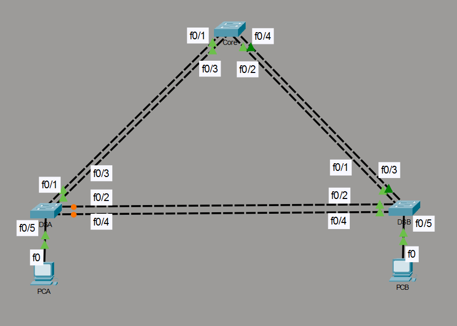
In enterprise campus networks, high availability requires redundant physical links between switches. However, redundant Layer 2 paths naturally introduce bridging loops and broadcast storms.
To resolve this, network engineers combine two essential Layer 2 technologies:
Spanning Tree Protocol (STP): Blocks redundant paths logically to maintain a loop-free topology.
EtherChannel (Link Aggregation): Bundles multiple physical interfaces into a single logical link, increasing bandwidth without triggering STP blocks on parallel links.
Lab Objective: Build a 3-switch topology where a single cable failure doesn’t disconnect users.
📁 Lab File: Download the Layer 2 Redundancy Packet Tracer Lab (.pkt).
Core Switch Configuration
The Core switch acts as the Root Bridge for the network. We also apply Root Guard to the interfaces facing the distribution switches to maintain stability.
! --- Basic Management ---
enable
configure terminal
hostname Core
spanning-tree mode rapid-pvst
spanning-tree vlan 1 root primary

! --- EtherChannel to DS-A (f0/1, f0/3) ---
interface range f0/1, f0/3
 channel-group 1 mode active
 switchport mode trunk
 spanning-tree guard root
exit

! --- EtherChannel to DS-B (f0/2, f0/4) ---
interface range f0/2, f0/4
 channel-group 2 mode active
 switchport mode trunk
 spanning-tree guard root
exit
DS-A Switch Configuration
This switch connects to the Core and maintains a redundant inter-switch link to DS-B. Note that ports facing access devices use PortFast and BPDU Guard to prevent end-user loops.
! --- Basic Management ---
enable
configure terminal
hostname DS-A
spanning-tree mode rapid-pvst

! --- EtherChannel to Core (f0/1, f0/3) ---
interface range f0/1, f0/3
 channel-group 1 mode active
 switchport mode trunk
exit

! --- EtherChannel to DS-B (f0/2, f0/4) ---
interface range f0/2, f0/4
 channel-group 3 mode active
 switchport mode trunk
exit

! --- PC Access Port ---
interface f0/5
 switchport mode access
 switchport access vlan 1
 spanning-tree portfast
 spanning-tree bpduguard enable
exit
DS-B Switch Configuration
DS-B mirrors the configuration of DS-A, ensuring it participates in all bundles.
! --- Basic Management ---
enable
configure terminal
hostname DS-B
spanning-tree mode rapid-pvst

! --- EtherChannel to Core (f0/1, f0/3) ---
interface range f0/1, f0/3
 channel-group 2 mode active
 switchport mode trunk
exit

! --- EtherChannel to DS-A (f0/2, f0/4) ---
interface range f0/2, f0/4
 channel-group 3 mode active
 switchport mode trunk
exit

! --- PC Access Port ---
interface f0/5
 switchport mode access
 switchport access vlan 1
 spanning-tree portfast
 spanning-tree bpduguard enable
exit
End-Device (PC) Configuration
To test connectivity across the switching fabric, configure PCA and PCB with static IPv4 addresses within VLAN 1 (default subnet 192.168.1.0/24). Assign static IP parameters via the GUI (Desktop > IP Configuration):
PCA Configuration (Interface f0)
- IP Address:
192.168.1.10 - Subnet Mask:
255.255.255.0 - Default Gateway:
192.168.1.1
PCB Configuration (Interface f0)
- IP Address:
192.168.1.20 - Subnet Mask:
255.255.255.0 - Default Gateway:
192.168.1.1
Verification
Once you apply the configurations, validate link aggregation, STP topology roles, and real-time failover behavior.
Verify EtherChannel Aggregation
Run
show etherchannel summaryacross your switches. Ensure member ports display the(P)flag (bundled in port-channel) rather than(D)(down) or(I)(stand-alone).Validate the STP Topology
Run
show spanning-tree vlan 1to verify root bridge placement and loop prevention:Core: Should display
This bridge is the root.DS-A or DS-B: One of the non-root Port-Channel interfaces must be in a
BLK(Blocking/Alternate) state to break the Layer 2 loop across the triangle topology.
Test Real-Time Convergence
Start a continuous ping from
PCAtoPCB(ping -t 192.168.1.20). While ICMP traffic is flowing, manually delete one of the active physical links in the forwarding path. Rapid PVST+ and EtherChannel should retain connectivity with minimal to zero dropped packets.