IPv4 address exhaustion makes public IP allocation scarce and expensive for enterprise networks. Port Address Translation (PAT), frequently referred to as NAT Overload, enables hundreds of internal hosts on private RFC 1918 subnets to share a single public IPv4 address for outbound internet access.
PAT operates by tracking source port numbers on outbound Layer 4 (TCP/UDP) headers. When private traffic exits the WAN boundary interface, the router maps the private Inside Local IP and port number to the router’s public Outside Global IP and a uniquely assigned source port.
Lab Objective: Configure an Access Control List (ACL) to match private LAN subnets, implement dynamic PAT using the
overloadkeyword on an outbound gateway interface, and verify port multiplexing state entries in the NAT translation table.
📁 Lab File: Download the NAT Overload Packet Tracer Lab (.pkt).
Topology
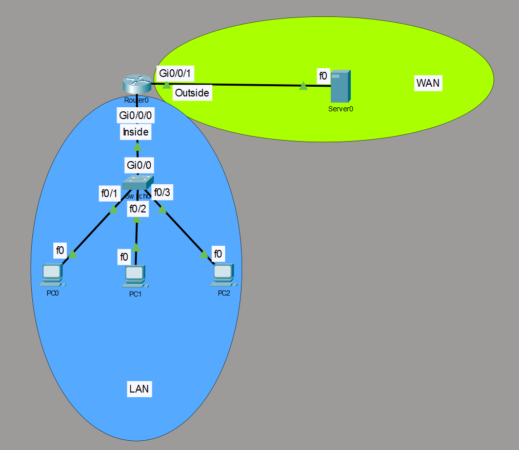
An edge router (Router0) connects an internal office network (192.168.10.0/24) on interface Gi0/0/0, and to an external ISP network (203.0.113.0/24) on Gi0/0/1. An external web server (Server0) resides on the WAN segment.
| Device | Interface | Role / NAT Domain | IP Address | Subnet Mask | Default Gateway |
|---|---|---|---|---|---|
| Router0 | Gi0/0/0 | Inside Interface (LAN) | 192.168.10.1 | 255.255.255.0 | N/A |
| Router0 | Gi0/0/1 | Outside Interface (WAN) | 203.0.113.1 | 255.255.255.0 | N/A |
| PC0 | Fa0 | Host Client | 192.168.10.2 | 255.255.255.0 | 192.168.10.1 |
| PC1 | Fa0 | Host Client | 192.168.10.3 | 255.255.255.0 | 192.168.10.1 |
| PC2 | Fa0 | Host Client | 192.168.10.4 | 255.255.255.0 | 192.168.10.1 |
| Server0 | Fa0 | Remote WAN Server | 203.0.113.2 | 255.255.255.0 | 203.0.113.1 |
Router Configuration
Configure NAT on the interfaces, define an internal ACL matching permitted LAN traffic, bind the ACL to the egress WAN interface using overload, and add a static default route to the ISP next-hop.
Router0 (Edge Gateway)
enable
configure terminal
hostname Router0

! --- 1. Interface Addressing & NAT Boundaries ---
interface GigabitEthernet0/0/0
 description Internal LAN Gateway
 ip address 192.168.10.1 255.255.255.0
 ip nat inside
 no shutdown
exit

interface GigabitEthernet0/0/1
 description External WAN Interface
 ip address 203.0.113.1 255.255.255.0
 ip nat outside
 no shutdown
exit

! --- 2. Define Permitted LAN Traffic via Standard ACL ---
access-list 1 permit 192.168.10.0 0.0.0.255

! --- 3. Enable PAT / NAT Overload on Public Interface ---
! Syntax: ip nat inside source list [ACL_#] interface [Outside_INT] overload
ip nat inside source list 1 interface GigabitEthernet0/0/1 overload

! --- 4. Default Static Gateway Route to ISP ---
ip route 0.0.0.0 0.0.0.0 203.0.113.2
exit
End-Host & Server Configurations
Configure static IP parameters on each end-device to match the topology and route internal traffic through the Router0 gateway.
Internal Host PCs (LAN Segment)
On each PC, navigate to Desktop > IP Configuration:
PC0
- IP Address:
192.168.10.2 - Subnet Mask:
255.255.255.0 - Default Gateway:
192.168.10.1
- IP Address:
PC1
- IP Address:
192.168.10.3 - Subnet Mask:
255.255.255.0 - Default Gateway:
192.168.10.1
- IP Address:
PC2
- IP Address:
192.168.10.4 - Subnet Mask:
255.255.255.0 - Default Gateway:
192.168.10.1
- IP Address:
Remote WAN Server (External Segment)
Configure the public WAN server representing your external internet/cloud destination:
- Server0
- IP Address:
203.0.113.2 - Subnet Mask:
255.255.255.0 - Default Gateway:
203.0.113.1
- IP Address:
Verification
Generate outbound ICMP traffic from internal hosts to the external WAN server, then inspect active port multiplexing entries and translation statistics on the edge gateway router.
Generate Outbound Traffic:
Open the Command Prompt on
PC0,PC1, andPC2and initiate pings toServer0(203.0.113.2):C:\> ping 203.0.113.2Verify Port Address Translations:
Execute
show ip nat translationsonRouter0to inspect active session mappings in the NAT table:Router0# show ip nat translations Pro Inside global Inside local Outside local Outside global icmp 203.0.113.1:1 192.168.10.2:1 203.0.113.2:1 203.0.113.2:1 icmp 203.0.113.1:2 192.168.10.2:2 203.0.113.2:2 203.0.113.2:2 icmp 203.0.113.1:3 192.168.10.2:3 203.0.113.2:3 203.0.113.2:3 icmp 203.0.113.1:4 192.168.10.2:4 203.0.113.2:4 203.0.113.2:4 icmp 203.0.113.1:5 192.168.10.2:5 203.0.113.2:5 203.0.113.2:5 icmp 203.0.113.1:6 192.168.10.2:6 203.0.113.2:6 203.0.113.2:6 icmp 203.0.113.1:7 192.168.10.2:7 203.0.113.2:7 203.0.113.2:7 icmp 203.0.113.1:8 192.168.10.2:8 203.0.113.2:8 203.0.113.2:8 Router0# show ip nat translations Pro Inside global Inside local Outside local Outside global icmp 203.0.113.1:1 192.168.10.3:1 203.0.113.2:1 203.0.113.2:1 icmp 203.0.113.1:2 192.168.10.3:2 203.0.113.2:2 203.0.113.2:2 icmp 203.0.113.1:3 192.168.10.3:3 203.0.113.2:3 203.0.113.2:3 icmp 203.0.113.1:4 192.168.10.3:4 203.0.113.2:4 203.0.113.2:4Result: Multiple internal RFC 1918 IPv4 addresses (
Inside local) are mapped to the exact same public IP address203.0.113.1(Inside global). The edge router appends unique source port numbers (e.g.,:1,:2) to track and distinguish each internal host session.Check NAT Statistics:
Review interface roles and active session counts using
show ip nat statistics:Router0# show ip nat statistics Total translations: 4 (0 static, 4 dynamic; 4 extended) Outside interfaces: GigabitEthernet0/0/1 Inside interfaces: GigabitEthernet0/0/0 Hits: 14 Misses: 15 Expired translations: 12 Dynamic mappings:Result: The output confirms boundary interface assignments (
Gi0/0/0inside,Gi0/0/1outside) and showsTotal translations: 4, as a result of a ping initiated from an internal PC.